Barrier-grid animations (also called scanimations) are a thing most people would recognize on sight, even if they didn’t know what they were called. Move a set of opaque strips over a pattern, and watch as different slices of that image are alternately hidden and revealed, resulting in a simple animation. The tricky part is designing the whole thing — but researchers at MIT designed FabObscura as a design tool capable not only of creating the patterned sheets, but doing so in a way that allows for complex designs.
 The barrier grid need not consist of simple straight lines, and movement of the grid can just as easily be a rotation instead of a slide. The system simply takes in the desired frames, a mathematical function describing how the display should behave, and creates the necessary design automatically.
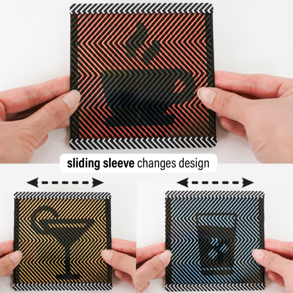
The paper (PDF) has more details, and while it is possible to make highly complex animations with this system, the more frames and the more complex the design, the more prominent the barrier grid and therefore the harder it is to see what’s going on. Still, there are some very nice results, such as the example in the image up top, which shows a coaster that can represent three different drink orders.
We recommend checking out the video (embedded below) which shows off other possibilities like a clock that looks like a hamster wheel, complete with running rodent. It’s reminiscent of this incredibly clever clock that uses a Moiré pattern (a kind of interference pattern between two elements) to reveal numerals as time passes.
We couldn’t find any online demo or repository for FabObscura, but if you know of one, please share it in the comments.
Continue reading “Design Scanimations In A Snap With The Right Math”