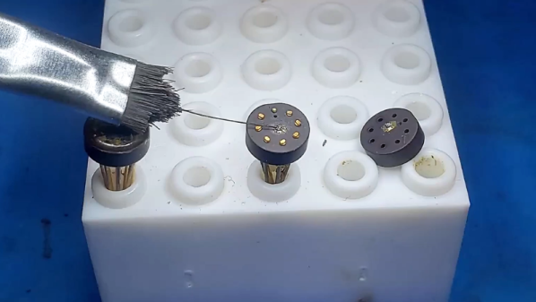
The Craziest Live Soldering Demo Is The Cyborg Ring

You can define the word crazy in myriad ways. Some would say using SMD resistors and QFN microcontrollers as structural elements is  crazy. Some would say hand soldering QFN is crazy, much less trying to do it on edge rather than in the orientation the footprint is designed for. And of course doing it live on stage in front of people who eat flux for breakfast is just bonkers. But Zach did it anyway and I’m delighted he did.

This is the cyborg ring, and it’s a one-of-a-kind leap in imagination — the kind of leap people have come to expect from Zach Fredin who modeled neurons on PCBs, depopulated an SMD LED matrix and airwired it, and replaced his ThinkPad fingerprint reader with an ARM debugger port. The construction leverages the precise nature of manufactured parts: the ATtiny85 that drives the ring is exactly twice the width of an 0805 component. This means he can bridge the two circuit boards that make up the ring with the QFN microcontroller, and then use two 10M Ohm resistors as structural spacers in a few places around the ring. The jewels in this gem of a project are red LEDs that can be addressed in an animated pattern.

There’s an adage that all live talk demos are doomed to fail, and indeed the uC in this project doesn’t want to speak to the programmer at the end of the 9-minute exhibition. But Zach did manage to solder the two halves on the ring together live on stage, and it’s worth enduring the camera issues and low starting volume at the start of this livestream to watch him perform some crazy magic. Good on you Zach for putting yourself out there and showing everyone that there’s more than one way to stack resistors.

If this demo leaves you wanting to hear more of what Zach’s adventures, we recommend checking out his 2016 Supercon talk on the Neurobytes development and manufacturing process.

Continue reading “The Craziest Live Soldering Demo Is The Cyborg Ring”

This Chromecast Volume Knob Has A Certain ’70s Chic

Chromecast devices have become popular in homes around the world in the last few years. They make it easy to cast audio or video from a smartphone or laptop, to a set of speakers or a display connected to the same network. [Akos] wanted to control the volume on these devices with a single, simple piece of equipment, rather than always reaching for a smartphone. Thus was built the CastVolumeKnob.

The project began by using Wireshark to capture data sent by the pychromecast library. Once [Akos] understood the messaging format, this was implemented in MicroPython on an ESP8266. A rotary encoder is used as a volume knob, and a Neopixel ring is used for visual feedback as to the device being controlled and the current volume level.

Further work was done to improve usability, with an ATtiny85 microcontroller being used to monitor the encoder for button presses before waking up the ESP8266, greatly reducing power consumption. The device is also rechargeable, thanks to an 18650 lithium polymer battery, and charger and boost converter boards. It’s all wrapped up in a sleek 3D printed case, with a translucent bezel for the LEDs and a swanky machined aluminium knob as the cherry on top.

It’s a homemade device that nonetheless would be stylish and unobtrusive in the living room environment. We imagine it proves very useful when important phone calls come in and it’s necessary to cut the stereo down to a more appropriate volume.

For another take, check out this USB volume knob with a nice weighty feel, courtesy of lead shot.

Interfacing The Sidewinder Joystick To AVRs

The Sidewinder line was a series of gaming peripherals produced by Microsoft, starting in the 1990s. After some initial stumbles, several cutting edge joysticks were released, at a time when the home computer market was in a state of flux, transitioning from legacy interfaces like serial and parallel to the more modern USB. In this interim period, Sidewinder joysticks used a special method to communicate digitally over the game port interface, which more typically used a kludge to read joysticks in an analog manner. [MaZderMind] managed to reverse engineer this protocol, and implemented the interface on an AVR microcontroller.

The technology is loosely described in US Patent 5628686, which discusses the method used to communicate bidirectionally with the Sidewinder joystick. [MaZderMind] found that the patent documents didn’t correspond exactly with how the Sidewinder Precision Pro communicated, but it was close enough that the operation could be reverse engineered.

The plan is to use the vintage joystick to control a quadcopter, so the interface was implemented on an AVR, and a graphical LCD installed to act as a display for testing the operation. [MaZderMind] also captured data on an oscilloscope to indicate in detail the quirks of the joystick’s operation.

Yes, it’s entirely possible to use a more modern microcontroller with a USB joystick. However, there are few that measure up to the standards of the old Sidewinder hardware, and sometimes the best tool for the job is the one you’ve got with you. A traditional single joystick is a different take on quadcopter control, but there’s other options – gesture control is possible, too.


Under The Hood Of Leica Camera Firmware

There’s nothing quite like waiting for something you’ve ordered online to arrive. In [Alex]’s case, he’d ordered a new Leica camera, only to find out there was a six month backlog in shipping. Wanting to whet his thirst regardless, he decided to investigate the Leica website, and reverse engineered a whole heap of camera firmware. As you do.

[Alex] didn’t stop at just one camera, instead spreading his interest across whatever firmware Leica happened to have online at the time. This approach led to improved effectiveness, as there were similarities in the firmware used between different cameras that made it easier to understand what was going on.

There are plenty of surprise quirks – from firmwares using the Doom WAD data format, to compression methods used by iD software in old game releases. [Alex]’s work runs the gamut from plotting out GUI icons on graph paper, to building custom tools to tease apart the operation of the code. Sample components were even sourced from connector manufacturers to reverse engineer various accessories, too.

[Alex]’s methodical approach and perseverance pays off, and it’s always interesting to get a look under the hood of the software underpinning consumer devices. We’ve even seen similar work done to decode the mysteries of Pokemon cries.

[Thanks to JRD for the tip!]


Polish Retro Silicon Brings This Computer To Life

It is an easy trap for us to write only about what we know when covering a topic, thus missing an entire facet of our subject matter. Take retrocomputing for example; we might write about American or Western European machines because we grew up with them, while completely ignoring the hardware being produced on the other side of the Iron Curtain.  Thus it’s fascinating to see [Marek Więcek]’s project, a single board retrocomputer employing a Polish clone of the Intel 8080.

With greater detail on a Polish-language forum (Google Translate), he tells a story of being given an MCY7880 CPU for his collection, only to wonder whether it could be made into a machine in its own right. As a clone of the 8080 this also required equivalents of the Intel bus controller and clock generator chips, which we are guessing must be the UCY74S405 and UCY7404 that he’s also sourced for the project.

The build is completed in true retro style with a maze of point-to-point wiring on the reverse of a protoboard, and he’s put a TinyBASIC interpreter port and 8251 UART on board as well as an 8255 triple parallel I/O port for some GPIO action. We love this computer, and appreciate the light it shines on an obscure corner of microprocessor history.

If Eastern European retrocomputing is your thing, here at Hackaday we’re lucky enough to number among our colleagues someone who’s something of an authority on the matter. [Voja Antonic] has entertained us with the tale of how he designed the Galaksija, Yugoslavia’s first home computer. Sadly though he did not use a Polish 8080 in his design.

Reworking MT3608 Boost Converters For Lower Idle Current Draw

The MT3608 is a popular boost converter, able to easily step up DC voltages in useful ranges, at an incredibly low cost. Modules can be sourced from eBay for less than $2, built on a PCB, ready to go. One drawback of these modules, particularly when working with batteries, is the idle current draw, on the order of 1 to 1.5mA. Fear not, however — there is a workaround, courtesy of [Aka Kasyan]. (Video, embedded below.)

The trick is to modify the behavior of the converter when no load is connected. The enable pin of the boost converter is held low through a pull-down resistor, keeping the boost converter switched off. In this state, the output voltage is equal to the input voltage. A current sense resistor is then installed in the output path. When a load is connected, this causes a voltage drop across the current sense resistor. This is then used to switch a transistor, which then connects the enable pin to the positive rail, switching the converter on, leading to the full boosted output voltage being reached.

[Aya] reports that this drastically cuts the idle current draw, which is particularly useful for battery powered projects. It’s important to note that the current sense resistor must be appropriately sized for the given load, however. If you’re a little hazy on the background, fear not — we’ve discussed the nature of boost converters before. Video after the break.

[Thanks to Baldpower for the tip!]
Continue reading “Reworking MT3608 Boost Converters For Lower Idle Current Draw”

Rebuilding The First Vocal Encryption System

Back in the early days of radio, it was quickly apparent that the technology would revolutionize warfare, but only if some way could be found to prevent enemies from hearing what was said. During World War II, the Allies put a considerable amount of effort into securing vocal transmissions, resulting in a system called SIGSALY – 50 tons of gear developed by Bell Laboratories with the help of Alan Turing that successfully secured communications between the likes of Churchill and Roosevelt during the war.

Now, a small piece of the SIGSALY system lives again, in the form of a period-faithful reproduction of the vocal quantizer used in the system. It’s the work of [Jon D. Paul], who undertook the build to better understand how the SIGSALY system worked. [Jon] also wanted to honor the original builders, who developed a surprisingly sophisticated system given the technology of the day.

SIGSALY was seriously Top Secret in the day, and most of the documentation was destroyed when the system was decommissioned. Working from scant information, [Jon] was able to recreate the quantizer from period parts, including five vintage VT-109/2051 thyratrons scrounged from eBay. The vacuum tubes are similar in operation to silicon-controlled rectifiers (SCRs) and form the core of the ADC, along with a resistor divider ladder network. Almost every component is period correct, and everything is housed in a nice acrylic case. It’s a beautiful piece of work and a great homage to a nearly forgotten piece of cryptographic history.

Interestingly, Bell Labs had a bit of a head start on the technology that went into SIGSALY, by virtue of their work on the first voice synthesizer in the 1930s.

Continue reading “Rebuilding The First Vocal Encryption System”