It Isn’t Rocket Science — Wait, Maybe It Is

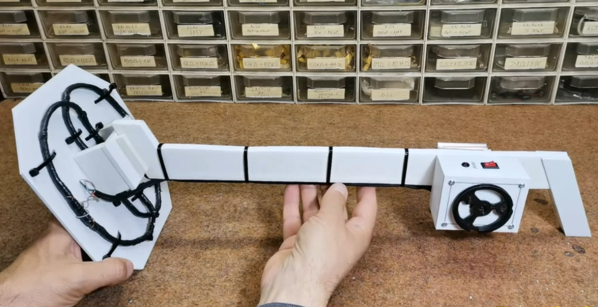
We don’t know why, but for some reason, the more dangerous something is, the more hacker appeal it seems to have. We like to deal with high temperatures, high voltages, dangerous chemicals, and powerful lasers. So [Tech Ingredient’s] recent video about homemade rocket motors certainly caught our attention. You may need a little commitment, though. The first video (yes, there isn’t just one) is over an hour long.

Turns out, [Tech] doesn’t actually want to use the rockets for propulsion. He needed a source of highly-ionized high-velocity plasma to try to get more power from his magnetohydrodynamic project. Whatever you want to use it for, these are serious-sized motors. [Tech] claims that his design is both powerful and easy to build. He also has a “secret” rocket fuel that he shares. What is it? We won’t spoil the video for you, but it is a sweet surprise.

Continue reading “It Isn’t Rocket Science — Wait, Maybe It Is”

Extremely Simple Tesla Coil With Only 3 Components

Tesla Coils are a favourite here at Hackaday – just try searching through the archives, and see the number of results you get for all types of cool projects. [mircemk] adds to this list with his Extremely simple Tesla Coil with only 3 Components. But Be Warned — most Tesla coil designs can be dangerous and ought to be handled with care — and this one particularly so. It connects directly to the 220 V utility supply. If you touch any exposed, conductive part on the primary side, “Not only will it kill You, it will hurt the whole time you’re dying”. Making sure there is an ELCB in the supply line will ensure such an eventuality does not happen.

No prizes for guessing that the circuit is straight forward. It can be built with parts lying around the typical hacker den. Since the coil runs directly off 220 V, [mircemk] uses a pair of fluorescent lamp ballasts (chokes) to limit current flow. And if ballasts are hard to come by, you can use incandescent filament lamps instead. The function of the “spark gap” is done by either a modified door bell or a 220 V relay. This repeatedly charges the capacitor and connects it across the primary coil, setting up the resonant current flow between them. The rest of the parts are what you would expect to see in any Tesla coil. A high voltage rating capacitor and a few turns of heavy gauge copper wire form the primary LC oscillator tank circuit, while the secondary is about 1000 turns of thinner copper wire. Depending on the exact gauge of wires used, number of turns and the diameter of the coils, you may need to experiment with the value of the capacitor to obtain the most electrifying output.

If you have to look for one advantage of such a circuit, it’s that there is not much that can fail in terms of components, other than the doorbell / relay, making it a very robust, long lasting solution. If you’d rather build something less dangerous, do check out the huge collection of Tesla Coil projects that we have featured over the years.

Continue reading “Extremely Simple Tesla Coil With Only 3 Components”

Circuit Sculpture Vibration Sensor

Here’s your useful and beautiful circuit for the day — [New Pew]’s vibration sensor takes manual control of the flip-flop inside a 555 timer and lights an LED in response. Use it to detect those vibrations you expect, like laundry machines, or those you only suspect, like the kind that might be coming from your engine. This gadget isn’t super-precise, but it will probably get the job done.

The vibration-detecting bit is a tiny ball bearing soldered to the spring from an old pen, which is tied between the trigger and ground pins of the 555. When the chip is powered with a 9 V battery, nearby vibrations will induce wiggle in the spring, causing the ball bearing to contact the brass rod and completing the circuit. When this happens, the internal flip flop’s output goes high, which turns on the LED. Then the flip flop must be reset with a momentary button. Check out the build video after the break.

Want to pick up Earthly vibrations? You can detect earthquakes with a homemade variable capacitor, a 555, and a Raspberry Pi.

Continue reading “Circuit Sculpture Vibration Sensor”

You Got Something On Your Processor Bus: The Joys Of Hacking ISA And PCI

Although the ability to expand a home computer with more RAM, storage and other features has been around for as long as home computers exist, it wasn’t until the IBM PC that the concept of a fully open and modular computer system became mainstream. Instead of being limited to a system configuration provided by the manufacturer and a few add-ons that really didn’t integrate well, the concept of expansion cards opened up whole industries as well as a big hobbyist market.

The first IBM PC had five 8-bit expansion slots that were connected directly to the 8088 CPU. With the IBM PC/AT these expansion slots became 16-bit courtesy of the 80286 CPU it was built around. These slots  could be used for anything from graphics cards to networking, expanded memory or custom I/O. Though there was no distinct original name for this card edge interface, around the PC/AT era it got referred to as PC bus, as well as AT bus. The name Industry Standard Architecture (ISA) bus is a retronym created by PC clone makers.

With such openness came the ability to relatively easy and cheaply make your own cards for the ISA bus, and the subsequent and equally open PCI bus. To this day this openness allows for a vibrant ecosystem, whether one wishes to build a custom ISA or PCI soundcard, or add USB support to a 1981 IBM PC system.

But what does it take to get started with ISA or PCI expansion cards today? Continue reading “You Got Something On Your Processor Bus: The Joys Of Hacking ISA And PCI”

Listening To Long Forgotten Voices: An Optical Audio Decoder For 16 Mm Film

Like many of us, [Emily] found herself on COVID-19 lockdown over the summer. To make the most of her time in isolation, she put together an optical audio decoder for old 16 mm film, built using modern components and a bit of 3D printing.

It all started with a broken 16 mm projector that [Emily] got from a friend. After repairing and testing the projector with a roll of film bought at a flea market, she discovered that the film contained an audio track that her projector couldn’t play. The audio track is encoded as a translucent strip with varying width, and when a mask with a narrow slit is placed over the top it modulates the amount of light that can pass through to a light sensor connected to speakers via an amplifier.

[Emily] used a pair of razor blades mounted to a 3D printed bracket to create the mask, and a TI OPT101 light sensor together with a light source to decode the optical signal. She tried to use a photoresistor and a discrete photodiode, but neither had the required sensitivity. She built a frame with adjustable positions for an idler pulley and the optical reader unit, an electronics box on one end for the electronic components, and another pulley attached to a stepper motor to cycle a short loop of the film.

Most of the projects we see involving film these days are for creating digital copies. You can digitize your old 35 mm photo film using a Raspberry Pi, some Lego pieces, and a DSLR camera, or do the same for 8 mm film with a 3D printed rig. Continue reading “Listening To Long Forgotten Voices: An Optical Audio Decoder For 16 Mm Film”

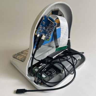
Magic 8-Ball Gets A Modern Makeover

Back in 2012, [sjm4306] was surprised when his breadboard rendition of the classic “Magic 8-Ball” popped up on Hackaday. If he had known the project was going to be enshrined on these hallowed pages, he might have tidied things up a bit. Now with nearly a decade of additional electronics experience, he’s back and ready to show off a new and improved version of the project.

The 3D printed case helps sell the look.

Conceptually, not much has changed from the original version. Press a button, get a random response. But on the whole the project is more refined, and not just because it’s moved over to a custom PCB.

The original version used a PIC16F886 with a charge controller and experimental RTC, but this time around [sjm4306] has consolidated all the functionality into the ATmega328P and is powering the whole thing with a simple CR2032 coin cell. As you can see in the video after the break, assembly is about as quick and straight-forward as it gets.

As with the original, there’s no accelerometer onboard. If you want to see a new message from your mystic companion, you’ve got to hold the button to “shake” the ball. A timer counts how long the button is held down, which in turn seeds the pseudorandom number generator that picks the response. Since each person will naturally hold the button for a slightly different amount of time, this keeps things from getting repetitive.

We don’t often see creators revisit their projects from the olden days, but we’d certainly like to. Consider this an open invitation to any hacker who wants to show off how much they’ve refined their skills; do-overs are always welcome here at Hackaday.

Continue reading “Magic 8-Ball Gets A Modern Makeover”

Printed Circuits, 1940s Style

A presentation this month by the Antique Wireless Museum brought British engineer and inventor John Sargrove (1906-1974) to our attention. If you’ve ever peeked inside old electronics from days gone by, you’ve no doubt seen point-to-point wiring and turret board construction. In the 60s and 70s these techniques eventually made way for printed circuit boards which we still use today. But Mr Sargrove was way ahead of his time, having already invented a process in the 1930s to print circuits, not just boards, onto Bakelite. After being interrupted by the war, he formed a company Electronic Circuit Making Equipment (ECME) and was building broadcast radio receivers on an impressive automatic production line.

Mr. Sargrove’s passion was making radios affordable for everyone. But to achieve this goal, he had to make large advances manufacturing technology. His technique of embedding not only circuit traces, but basic circuit elements like resistors, capacitors, and inductors directly into the substrate foresaw techniques being applied decades later in integrated circuit design.  He also developed a compact vacuum tube which could be used in all circuits of a radio, called an “All-stage Valve“. Equally important was his futuristic automatic factory, which significantly reduced the number of factory workers needed to make radios from 1500 to 50. Having completed the radio design, he was also developing a television receiver using the same concepts. Unfortunately, ECME was forced into liquidation when a large order from India was cancelled upon declaration of independence in 1947.

You really must watch the video below. There are many bits and pieces of modern factory automation which we still use today, yet their implementation using 1940s techniques and technology is fascinating. Further reading links after the video. Thanks to [Mark Erdle] for the tip.

Continue reading “Printed Circuits, 1940s Style”