A stepper-powered flip clock

Steppers And ESP32 Make This Retro-Modern Flip-Clock Tick

Before LEDs became cheap enough to be ubiquitous, flip-card displays were about the only way to get a digital clock. These entirely electromechanical devices had their own charm, and they have a certain retro cachet these days. Apart from yard sales and thrift stores, though, they’re a bit hard to source — unless you roll your own, of course.

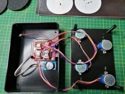
Granted, [David Huang]’s ESP32-based flip clock is worlds apart from the flip cards of the “I Got You, Babe” era. Unfortunately, the video below is all we have to go on to get the story behind this clock, but it’s pretty self-explanatory. [David] started the build by making the flip cards themselves, a process that takes some topological tricks as well as a laser cutter. 3D-printed spools are loaded with the cards, which are then attached to frames that hold a stepper motor and a Hall-effect sensor. The ESP32 drives the steppers via L298N H-bridge drivers, but it’s hard to say if there’s an RTC chip or if the microcontroller is just getting time via an NTP server.

[David] might not be the only one trying to recapture that retro look, but we’ve got to hand it to him — it’s a great look, and it takes a clever maker to not only build a clock like this, but to make a video that explains it all so clearly without a single word of narration.

Continue reading “Steppers And ESP32 Make This Retro-Modern Flip-Clock Tick”

VFD clock with wood case

Captivating Clock Puts Endangered Displays On Display

The DT-1704A VFD is straight from the 1976 Radio Shack Catalog
The DT-1704 VFD as seen the 1976 Radio Shack Catalog. The “A” version has no substrate, making the VFD fully clear for added effect.

When you have a small stock of vacuum fluorescent displays (VFDs) straight out of the 1976 Radio Shack catalog, you might sit around wondering what to do with them. When [stepawayfromthegirls] found out that his stash of seven DT-1704A tubes may be the last in existence, there was no question. They must be displayed! [stepawayfromthegirls]’ mode of display is this captivating clock build. Four VFDs with their aqua colored elements are set against a black background in a bespoke wooden case. Looking under the hood, the beauty only increases.

VFD Clock Wiring is almost as stunning as the clock itself
VFD Clock Wiring is nearly as stunning as the clock itself.

Keeping the build organized was not an easy task because the tubes are designed in such a way that each segment must be individually controlled. The needed I/O duties are provided by an Arduino Mega 2560 Pro (Embed). 28 2n3904’s each with their two resistors serve as drivers for each VFD segment.

The output of a  24 V AC transformer left over from the 1980s is rectified to 34 V of DC power which is then regulated to 27 V to power the tubes. Switching power supplies provide 6 V to the Arduino and 1.3 V to the filaments. If you look closely, you’ll also see a GPS module so that the clock doesn’t need to be set. To future-proof the clock against daylight savings time adjustments, a potentiometer on the back of the case allows the user to set custom hour offsets without editing any code.

We think the end result is a remarkably clean, simple, and elegant clock that he will be proud of for many years to come!

If VFD clock builds are your thing, then you’ll enjoy this Network Attached VFD Clock and a Mini VFD Clock with floating display.  And while not VFD based, we’d be silly to leave out the Boat Anchor Nixie Clock with enough knobs, switches, and buttons to delight even the fussiest of hacker.


A wall clock with exposed circuit boards

Drunk Wall Clock Uses Convoluted Circuits To Display Time

Here at Hackaday we can never get enough of odd clocks, and we’re delighted to see [Dan O’Shea]’s creation called the Wifi-Telnet-FPGA-NTSC Drunk Wall Clock. That mouthful is an accurate description of what it does: at the heart of the device is an ESP32 that uses WiFi to connect to a Raspberry Pi. It then telnets into the system, logs in, and requests the current time using the Linux date command. So far, so ordinary.

The “FPGA” part is where it gets weirder: the ESP32 is hooked up to a VGA1306 board. This is a little PCB with an FPGA that emulates an OLED display and outputs the image to a VGA connector. [Dan] could have simply hooked up a VGA display to this, but instead went for another layer of complexity by converting the VGA signal to something resembling composite video, using nothing more than three resistors. The resulting “NTSC” signal is then fed into a small TFT display that shows the time.

The clock got its “drunk” label because the process of repeatedly running the date command and parsing its output is slow and prone to hiccups, resulting in a display where the seconds advance in a somewhat unsteady manner. This fits well with the overall aesthetic of the clock, which consists of a heap of PCBs held together with cable ties and electrical tape. Mounted on a round panel of recycled wood, it makes a beautiful wall ornament for any hacker lab.

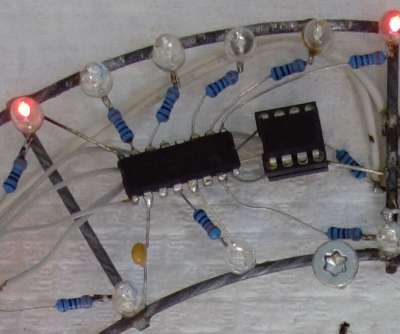
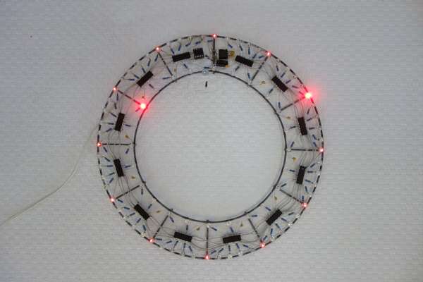
We love projects like this that accomplish a simple task in a convoluted way, and there’s no shortage of needlessly complicated clocks, whether physically drawing the time or using machine-learning data. But if you simply like your clocks with their electronics exposed, check out this free-form LED clock or this neat circuit sculpture clock.

Continue reading “Drunk Wall Clock Uses Convoluted Circuits To Display Time”

Cast-in-Concrete Clock Upgraded After Thirteen Years

Proving that an old design cast in concrete can indeed be changed, [Hans Jørgen Grimstad] has revisited his Nixie clock from 2008, cleaned up the electronics and packaging, and turned it into a kit. Not that he has plans to enter the kit-making business, but he just thought it would be fun to learn how to make kits. In the video below the break, he’s a bit embarrassed to reveal the inside of his first Nixie clock design, housed in a cast-concrete electronics enclosure. Although it still works, the internal wiring is a flaky, untidy, and perhaps a bit dangerous.

But [Hans] has improved his game over the years, making a number of different clock designs. The latest incarnation is pleasant to look at, built on a PCB which is visible inside a custom acrylic case. Three versions are available to support different types of tubes. The documentation he prepared for the project and the kit is very thorough. He walks you through the unboxing and assembly process in the videos below. Firmware is in C, and runs on a Raspberry Pi Zero W. If you are interesting in making electronics kits, [Hans]’s project would be a good example to follow.

All the necessary information to build the clock is published on the project’s GitHub repository. If you’re looking for enclosure ideas other than concrete or acrylic sheet, check out this write-up on hand-forging artistic Nixie clock enclosures.

Continue reading “Cast-in-Concrete Clock Upgraded After Thirteen Years”

an image of maketime showing the current time

Unique Clock Doubles As A Development Board

Most clocks these days have ditched the round face and instead prefer to tell time through the medium of 7-segment displays. [mihai.cuciuc] is bringing the round face to digital clocks with his time-keeping piece, MakeTime.

MakeTime's custom PCBMakeTime serves two purposes, the first and most obvious one is as a clock. Rather than displaying the time with digits, MakeTime harkens back to round dial clocks by illuminating RGB LEDs along its perimeter to show the position of the minute and hour “hands”. By using 24 LEDs, MakeTime achieves a timing granularity of 2.5 minutes.

The second purpose is as a development platform. [mihai.cuciuc] designed the clock with hacking in mind, opting to build it with components that many are already familiar with, such as a DS3231 RTC and WS2812 LEDs. To make the entire thing Arduino compatible, the microcontroller is an AtMega 328P, that can be connected to through the micro-USB port and CH340 USB-UART IC. If MakeTime outlives its time as a clock, all of the unused GPIO of the 328P are broken out to a single pin header, allowing it to be repurposed in other projects for years to come.

It seems like everyone is making their own unique timekeeping device these days. Check out the clock made out of ammeters we covered last week.

Useless Machine Is A Clock

Useless machines are a fun class of devices which typically turn themselves off once they are switched on, hence their name. Even though there’s no real point, they’re fun to build and to operate nonetheless. [Burke] has followed this idea in spirit by putting an old clock he had to use with his take on a useless machine of sorts. But instead of simply powering itself off when turned on, this useless machine dislodges itself from its wall mount and falls to the ground anytime anyone looks at it.

It’s difficult to tell if this clock was originally broken when he started this project, or if many rounds of checking the time have caused the clock to damage itself, but either way this project is an instant classic. Powered by a small battery driving a Raspberry Pi, the single-board computer runs OpenCV and is programmed to recognize any face pointed in its general direction. When it does, it activates a small servo which knocks it off of its wall, rendering it unarguably useless.

[Burke] doesn’t really know why he had this idea, but it’s goofy and fun. The duct tape that holds everything together is the ultimate finishing touch as well, and we can’t really justify spending too much on fit and finish for a project that tosses itself around one’s room. On the other hand, if you’re looking for a more refined useless machine, we have seen some that have an impressive level of intricacy.

Thanks to [alchemyx] for the tip!

Continue reading “Useless Machine Is A Clock”

ClOCkTAL: For When Reading A Clock Is Just Too Easy

Over on Hackaday.io, [danjovic] presents clOCkTAL, a simple LED clock for those of us who struggle with the very concept of making it easy to read the time. Move aside binary clocks, you’re easy, let’s talk binary coded octal. Yes, it is a thing. We’ll leave it to [danjovic] to describe how to read the time from it:

Do not try to do the math using 6 bits. The trick to read this clock is to read every 3-bit digit in binary and multiply the MSBs by 8 before summing to the LSBs.

Simple. If you’re awake enough, that is. Anyway, we’re a big fan of the stripped-down raw build method using perf board, and scrap wood. No details hidden here. The circuit is straightforward, being based on a minimal configuration needed to drive the PIC16F688 and a handful of LEDs arranged in a 3×4 matrix.

An interesting detail is the use of Bresenham’s Algorithm to derive the one event-per-second needed to keep track of time. And no, this isn’t the more famous Bresenham’s line algorithm you may be more familiar with, it’s much simpler, but does work on the same principle of replacing expensive arithmetic division operations with incremental errors. The original Bresenham’s Algorithm was devised for using with X-Y plotters, which had limited resolution, and was intended to allow movements that were in an imperfect ratio to that resolution. It was developed into a method for approximating lines, then extended to cover circles, ellipses and other types of drawables.

Continue reading “ClOCkTAL: For When Reading A Clock Is Just Too Easy”