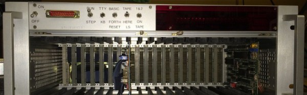
Today when you want to upgrade your computer you slap in a card, back in the early 80’s things were not always as simple. When [Carsten] was digging around the house he found his old, and heavily modified Rockwell AIM 65 single board computer, flipped the switch and the primitive 6502 machine popped to life.
Added to the computer was a pile of wires and PCB’s in order to expand the RAM, the I/O to form a “crate bus” and of course tons of LED blinkenlights! On that bus a few cards were installed, including a decoder board to handle all the slots, a monitor controller, a massive GPIO card, and even a universal EEPROM programmer.
If that was not enough there was even a OS upgrade from the standard issue BASIC, to a dual-boot BASIC and FORTH. Though again unlike today where upgrading your OS requires a button click and a reboot, making all these upgrades are planned out on paper, which were scanned for any retro computer buff to pour through.
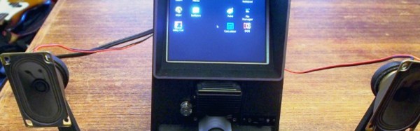
[Carsten] posted a video of this computer loading the CRT initilization program from a cassette. You can watch, but shouldn’t listen to that video here.
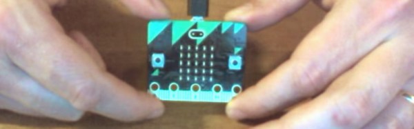
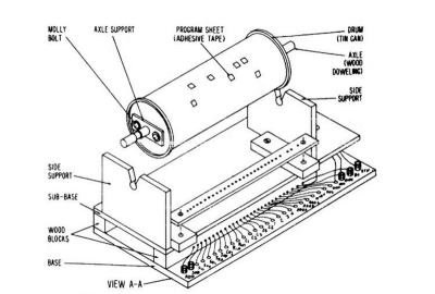 So what did you do if you were a kid saving money from a paper route in 1968 and you wanted to build a computer? Maybe you turned to
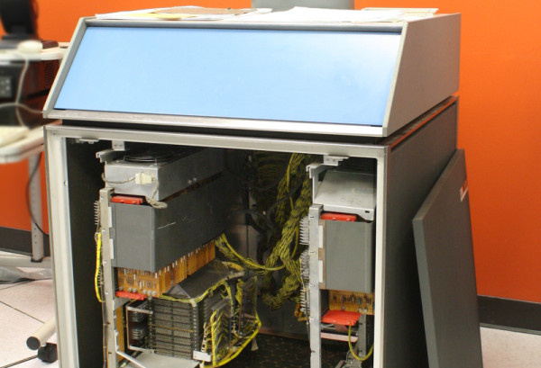
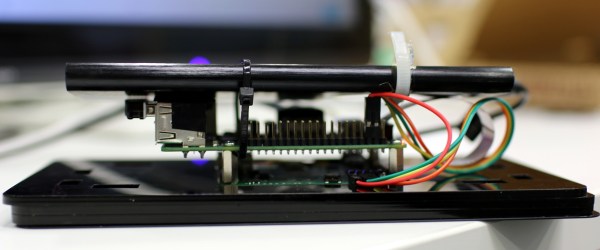
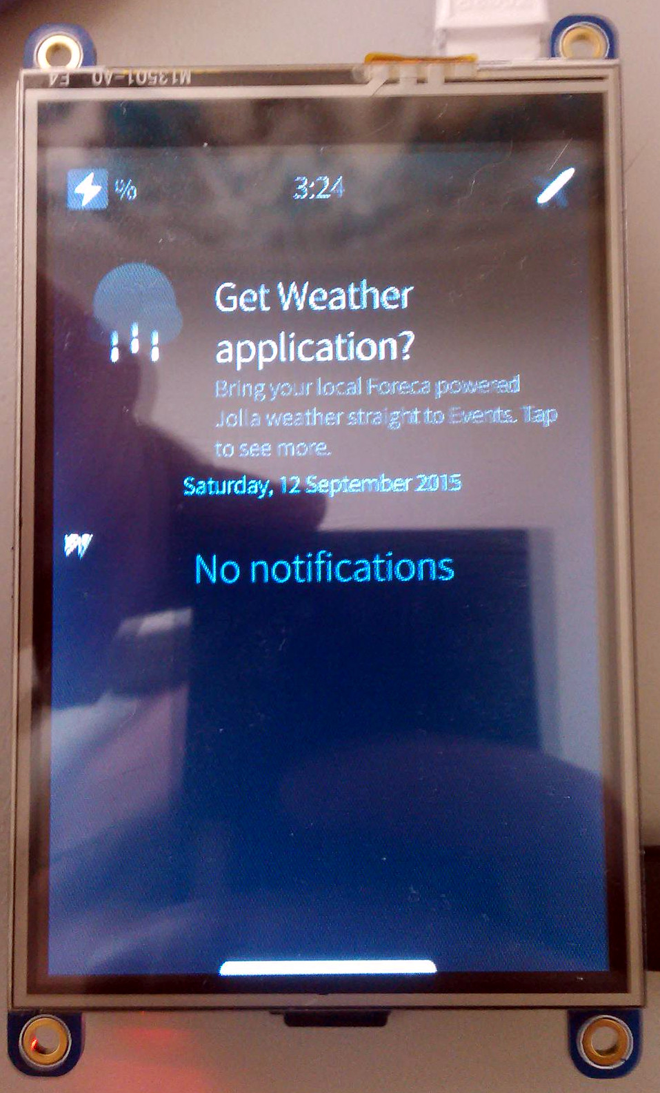 The creator, [Aleksi Suomalainen] expended a lot of effort pulling all the pieces together on this project.