AirAsia Crash Analysis: Who Or What Failed?

Just a few days after Christmas last year AirAsia Flight 8051 traveling to Singapore tragically plummeted into the sea. Indonesia completed its investigation of the crash and just released the final report. Media coverage, especially in Asia is big. The stories are headlined by pilot error but,as technologists, there are lessons to be learned deeper in the report.

The Airbus A320 is a fly-by-wire system meaning there are no mechanical linkages between the pilots and the control surfaces. Everything is electronic and most of a flight is under automatic control. Unfortunately, this also means pilots don’t spend much time actually flying a plane, possibly less than a minute, according to one report.

Here’s the scenario laid out by the Indonesian report: A rudder travel limit computer system alarmed four times. The pilots cleared the alarms following normal procedures. After the fifth alarm, the plane rolled beyond 45 degrees, climbed rapidly, stalled, and fell.

Continue reading “AirAsia Crash Analysis: Who Or What Failed?”

Fail Of The Week: OpenMV Kickstarter Project Hits Manufacturing Snag

Making stuff is hard, especially when you are making lots of stuff. The OpenMV Cam project knows this, because it has hit a problem while putting together their cheap machine vision module. The problem is with the BGA solder balls that connect the image sensor to the main board.

openmv-thumbWe’ve covered this intriguing project before: the aim is to build a small, cheap module that can run image processing algorithms to easily give robots sight. The sensor is a Ball Grid Array (BGA) package, which means there are a grid of small solder balls on the back that form the electrical connections. It seems that some of these solder balls are oxidized, preventing them from melting and fusing properly with the board. This is called a head-in-pillow defect, because the ball behaves like your head when you lie down in bed. Your head squishes the pillow, but doesn’t merge into it. There are 38 balls on the OV26040 image sensor and even a single bad link means a failure.

The makers of the project have tried a number of solutions, but it seems that they may have to remake the ball links on the back of each sensor. That’s an expensive process: they say it will cost $7 for each, more than the actual sensor cost initially.

A few people have been posting suggestions in the comments for the project, including using solvents and changing the way the sensors are processed before mounting. We’d like to see them overcome this hurdle. Anybody have any suggestions to quickly and cost effectively move the manufacturing process forward?

Continue reading “Fail Of The Week: OpenMV Kickstarter Project Hits Manufacturing Snag”

Fail Of The Week: Exploding Fermentation

It’s no secret that hackers like fermentation, both the process and the end results. I myself have a crock of sauerkraut happily bubbling away in the kitchen right now. Fermentation can lead to tasty endpoints, and the process itself, which basically amounts to controlled rotting, is a fascinating set of biochemical reactions. But done wrong, fermentation can result in injury, as it did at CCC this year when a fermentation vessel exploded.

"It was the one on the left, officer. He did it."
“It was the one on the left, officer. He did it.”

Exactly what happened isn’t really clear, except that Food Hacking Base ran a number of workshops at CCC 2015, several of which involved fermented foods or drinks. A Grolsch-style bottle with a ceramic flip-top was apparently used as a fermentation vessel, but unfortunately the seal was not broken. The bottle found its way to another tent at CCC, this one running an SMD soldering workshop. Carbon dioxide gas built up enough pressure in the bottle to shatter it and send shrapnel flying through the workshop tent. According to a discussion thread on the incident, “people got hurt and need to go to the hospital because glas [sic] particles were stuck in their faces, a throat was cut and an eyelid bleeding.” The explosion was quite energetic, because, “we also found a 20cm long piece of glass that went trough [sic] the ceiling of the tent and propelled for another 4-5 meters afterwards.”

We’ve seen lots of Hackaday projects involving instrumentation and automation of fermentation, including some with really large vessels. The potential for destruction if such a vessel isn’t properly vented is pretty high. At the very least, you’ll be left with a really big mess to clean up. Be careful out there – microbes are not to be trifled with. We don’t want to give you the wrong idea about CCC; this year was incredible as [Elliot Williams] reported during his time there.

Now it’s off to the kitchen to check on my kraut.

[Thanks to Morgan for the tip.]

Fail Of The Week: The Deadliest Multimeter

Need a good multimeter? The Fluke 17B is an excellent basic meter that will last your entire career. It’s also $100 USD. Need something cheaper? Allow me to introduce the AIMOmeter MS8217. On the outside, it’s a direct copy of the Fluke 17b, right down to the screen printing but understandably lacking the yellow enclosure. $30 USD will get you an exact copy of a Fluke 17B, it would seem. Right? Not a chance. [electronupdate] did a teardown of the AIMOmeter, and while this meter looks like a Fluke on the outside, it’s probably going to kill somebody.

The teardown begins with a look at the ratings on the back of this off-brand meter. It does have two fuses, but the engraving on the back strangely claims ‘Wrrebt insurance limit’. If anyone has any idea what a ‘wrrebt’ is, please leave a note in the comments. The only references to this word in Google are mis-OCRed blackletter type in a book from the early 1800s.

Opening up the meter reveals – surprisingly – two real fuses in the meter. There were no markings on the bigger fuse, which could be a problem for verifying if the fuse is of the proper value. That’s not really a problem, though: the fuse isn’t even between ground and the amp probe socket. Yes, this fuse is completely useless, and testing the resistance with the fuse out of the circuit confirms this.

After putting the meter back together, [electron] tests the accuracy of the meter. With a 1 mA current source, the mA setting seems to work, but when testing the larger Amp range of this meter, the results display in milliVolts. Don’t worry, there’s an easy fix for that: just press the dial down just right and the correct setting will be displayed. Wow.

You get what you pay for, and if you only ever use an AIMOmeter for measuring Arduinos and batteries, you might – might – be alright. This is not the kind of meter you want to measure line voltage, motors, or anything else with, though.

Hackaday Fail: A $3000 Prototype That Doesn’t Work

[Dan Royer] is hard at work building his own personal robot army. Robots mean motors, and motors mean gearboxes. In [Dan]’s case, gearboxes mean $3000 wasted on a prototype that doesn’t work. Why doesn’t it work? He doesn’t know, and we don’t either.

[Dan] would like to use small but fast DC motors for his robots coupled to a gearbox to step down the speed and increase the torque. The most common way of doing this is with a planetary gear set, but there’s a problem with the design of planetary gears – there is inherent backlash and play between the gears. This makes programming challenging, and the robot imprecise.

A much better way to gear down a small DC motor is a hypocycloid gear. If you’ve ever seen the inside of a Wankel engine, this sort of gearing will look very familiar: a single gear is placed slightly off-axis inside a ring gear. On paper, it works. In reality, not so much.

[Dan] spent $3000 on a prototype hypocycloid gearbox that doesn’t turn without binding or jamming. The gear was made with incredible tolerances and top quality machining, but [Dan] has a very expensive paper weight sitting on his desk right now.

If anyone out there has ever designed or machined a hypocycloid gearbox that works, your input is needed. The brightest minds [Dan] met at the Bring A Hack event at Maker Faire last weekend could only come up with. ‘add more lasers’, but we know there’s a genius machinist out there that knows exactly how to make this work.


2013-09-05-Hackaday-Fail-tips-tileHackaday Fail is a column which runs every now and again. Help keep the fun rolling by writing about your past failures and sending us a link to the story — or sending in links to fail write ups you find in your Internet travels.

Fail Of The Week: Re-addressing Your RAM DIMM

It doesn’t work and we’re not surprised considering the can of worms that comes with RAM addressing. Right off the bat we assume timing problems due to variance in the trace lengths and EM issues. But you have to hand it to [cyandyedeyecandy] for even trying. The self-proclaimed upgrade seeks to readjust how the DIMM works without changing the edge pinout.

The stick shown here is a 512 MB module that, because of the computer using it (unspecified in the post), is only allowing access to 256 MB. The added chips and free-form circuit make up an AND for the chip-select line, and flip-flop for the bank address.

The post is a gorgeous cry for help. We already weighed in from the peanut gallery at the top (seriously, that’s somewhat baseless guessing) so step up to the computer-engineering plate and let us know what needs to be done to make this most-awesome-of-non-working hacks actually work.

Once you’ve figured this out, here’s another one to scratch at your brain with.

Fail Of The Week : Measuring DC Current Has To Be Easy, Right?

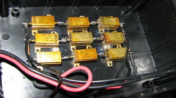
[DainBramage] needed a DC ammeter to check how long his amateur radio station would be able to stay powered on battery backup power. The one’s he already had on hand were a Clamp Meter, which could only measure AC, and another one that measured just a few milliamps. Since he didn’t have one which could measure up to 25A, he decided to build his own DIY DC Ammeter with parts scavenged from his parts bin. Measuring DC current is not too difficult. Pass the current to be measured through a precision resistor, and measure the voltage drop across it using a sensitive voltmeter.

I = V/R

So far, so good. If it’s late at night and you’ve had a lot of coffee, busy building your DC ammeter, things could head south soon. [DainBramage]’s first step was to build a suitable Shunt. He had a lot of old, 1Ω, 10W resistors lying around. He made a series-parallel combination using nine of them to create a hefty 1Ω, 90W shunt (well, 0.999999999 Ohms if you want to be picky). This gave him a nice 1 Volt per Amp ratio, making it easy to do his measurements.

Next step was to hook up the shunt to a suitable voltmeter. Luckily, he had a Micronta voltmeter lying around, ripped out from a Radio Shack product. Since he didn’t have the voltmeter data, he hooked up a 10k resistor across the meter inputs, and slowly increased the voltage applied to the meter. At 260mV, the needle touched full-scale and the voltage across the inputs of the voltmeter was 33mV. [DainBramage] then describes the math he used to calculate the resistors he would need to have a 10A and a 25A measurement range. He misses his chance to catch the fail. His project log then describes some of the boring details of putting all this together inside a case and wrapping it all up.

A while later, his updates crop up. First thing he probably realized was that he needed more accurate readings, so he added connectors to allow attaching a more accurate voltmeter instead of the analog Micronta. At this point, he still didn’t catch the fail although it’s staring him straight in the face.

His head scratching moment comes when he tries to connect his home made ammeter in series with the 12V DC power supply to his amateur radio station. Every time he tries to transmit (which is when the Radio is drawing some current), the Radio shuts off.  If you still haven’t spotted the fail, try figuring out how much voltage gets dropped across the 1Ω shunt resistor when the current is 1A and when it is 5A or more.