Retrotechtacular: Circuit Boards The Tektronix Way

Printed circuit boards are a fundamental part of both of commercial electronic equipment and of the projects we feature here on Hackaday. Many of us have made our own, whether done so from first principles with a tank of etchant, or sent off as a set of Gerbers to a PCB fab house.

To say that the subject of today’s Retrotechtacular is the manufacture of printed circuit boards might seem odd, because there is nothing archaic about a PCB, they’re very much still with us. But the film below the break is a fascinating look at the process from two angles, both for what it tells us about how they are still manufactured, and how they were manufactured in 1969 when it was made.

Board artwork laid out at four-times actual size

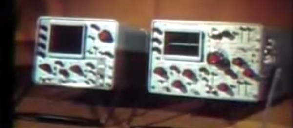
Tektronix were as famous for the manufacturer of particularly high quality oscilloscopes back then as they are now. The Tektronix ‘scopes of the late 1960s featured several printed circuit boards carrying solid-state electronics, and were manufactured to an extremely high standard. The film follows the manufacturing process from initial PCB layout to assembled board, with plenty of detail of all production processes.

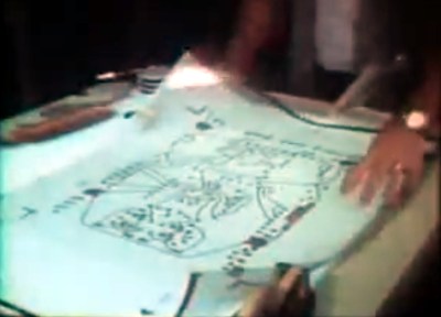
In 2017 you would start a PCB design in a CAD package, but in 1969 the was incredibly manual. Everything was transcribed by hand from a paper schematic to transparent film. Paper mock-ups of component footprints four times larger than actual size are placed on a grid, and conductors drawn in pencil on an overlaid piece of tracing paper. Then the pads and pattern of tracks are laid out using black transfers and tape on sheets of film over the tracing paper, one each for top and bottom of the board. A photographic process reduces them to production size onto film, from which they can be exposed and etched in the same way that you would in 2017.

Pantograph drilling machine uses a manually moved styuls on a template to drill six boards at once

Most of the physical process of creating a PCB has not changed significantly since 1969. We are shown the through-plating and gold plating processes in detail, then the etching and silkscreening processes, before seeing component installation and finally wave soldering.

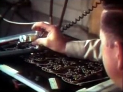
What are anachronistic though are some of the machines, and the parts now robotised that were done in 1969 by hand. The PCB drilling is done by hand with a pantograph drill for small runs, but for large ones a fascinating numerically-controlled drilling rig is used, controlled by punched tape without a computer in sight. Component placement is all by hand, and the commentator remarks that it may one day be done by machine.

The film remains simultaneously an interesting look at PCB production and a fascinating snapshot of 1960s manufacturing. It’s probable that many of the Tek ‘scopes made on that line are still with us, they’re certainly familiar to look at from our experience at radio rallies.

Continue reading “Retrotechtacular: Circuit Boards The Tektronix Way”

Retrotechtacular: How To Repair A Steam Locomotive

Steam locomotives, as a technological product of the 19th century, are not what you would imagine as fragile machines. The engineering involved is not inconsequential, there is little about them that is in any way flimsy. They need to be made in this way, because the huge energy transfer required to move a typical train would destroy lesser construction. It would however be foolish to imagine a locomotive as indestructible, placing that kind of constant strain on even the heaviest of engineering is likely to cause wear, or component failure.

A typical railway company in the steam age would therefore maintain a repair facility in which locomotives would be overhauled on a regular basis, and we are lucky enough to have a 1930s film of one for you today courtesy of the British London Midland and Scottish railway. In it we follow one locomotive from first inspection through complete dismantling, lifting of the frame from the wheels, detaching of the boiler, inspection of parts, replacement, and repair, to final reassembly.

We see steps in detail such as the set-up of a steam engine’s valve gear, and it is impressed upon us how much the factory runs on a tight time schedule. Each activity fits within its own time window, and like a modern car factory all the parts are brought to the locomotive at their allotted times. When the completed locomotive is ready to leave the factory it is taken to the paint shop to emerge almost as a new machine, ready for what seems like a short service life for a locomotive, a mere 130 thousand miles.

The video, which we’ve placed below the break, is a fascinating glimpse into the world of a steam locomotive servicing facility. Most Hackaday readers will never strip down a locomotive, but that does not stop many of them from having some interest in the process. Indeed, keen viewers may wish to compare this film with “A Study in Steel“, another film from the LMS railway showing the construction of a locomotive.

LMS Jubilee class number 5605, “Cyprus”, the featured locomotive in this film, was built in 1935, and eventually scrapped in 1964 as part of the phasing out of steam traction on British railways.

Continue reading “Retrotechtacular: How To Repair A Steam Locomotive”

Retrotechtacular: Weather Station Kurt

Sometimes when researching one Hackaday story we as writers stumble upon the one train of thought that leads to another. So it was with a recent look at an unmanned weather station buoy from the 1960s, which took us on a link to a much earlier automated weather station.

The restored Kurt in the Canadian National War Museum.

Weather Station Kurt was the only successful installation among a bold attempt by the German military during the Second World War to gain automated real-time meteorological data from the Western side of the Atlantic. Behind that simple sentence hides an extremely impressive technical and military achievement for its day. This was the only land-based armed incursion onto the North American continent by the German military during the entire war. Surrounded as it was though by secrecy, and taking place without conflict in an extremely remote part of Northern Labrador, it passed unnoticed by the Canadian authorities and was soon forgotten as an unimportant footnote in the wider conflagration.

Kurt took the form of a series of canisters containing a large quantity of nickel-cadmium batteries, meteorological instruments, a telemetry system, and a 150W high frequency transmitter. In addition there was a mast carrying wind speed and direction instruments, and the transmitting antenna. In use it was to have provided vital advance warning of weather fronts from the Western Atlantic as they proceeded towards the European theatre of war, the establishment of a manned station on enemy territory being too hazardous.

A small number of these automated weather stations were constructed by Siemens in 1943, and it was one of them which was dispatched in the U-boat U537 for installation on the remote Atlantic coast of what is now part of modern-day Canada. In late October 1943 they succeeded in that task after a hazardous trans-Atlantic voyage, leaving the station bearing the markings of the non-existent “Canadian Meteor Service” in an attempt to deceive anybody who might chance upon it. In the event it was not until 1977 that it was spotted by a geologist, and in 1981 it was retrieved and taken to the Canadian War Museum.

There is frustratingly little information to be found on the exact workings on the telemetry system, save that it made a transmission every few hours on 3940kHz. A Google Books result mentions that the transmission was encoded in Morse code using the enigmatic Graw’s Diaphragm, a “sophisticated contact drum” named after a Dr. [Graw], from Berlin. It’s a forgotten piece of technology that defies our Google-fu in 2017, but it must in effect have been something of a mechanical analogue-to-digital converter.

Should you happen to be visiting the Canadian capital, you can see Kurt on display in the Canadian War Museum. It appears to have been extensively restored from the rusty state it appears in the photograph taken during its retrieval, it would be interesting to know whether anything remains of the Graw’s Diaphragm. Do any readers know how this part of the station worked? Please let us know in the comments.

Weather station Kurt retrieval image, Canadian National Archives. (Public domain).

Weather station Kurt in museum image, SimonP (Public domain).

Retrotechtacular: Radio To Listen To When You Duck And Cover

CONELRAD may sound like the name of a fictional android, but it is actually an acronym for control of electronic radiation. This was a system put in place by the United States at the height of the cold war (from 1951 to 1963) with two purposes: One was to disseminate civil defense information to the population and, also, to eliminate radio signals as homing beacons for enemy pilots.

Continue reading “Retrotechtacular: Radio To Listen To When You Duck And Cover”

Retrotechtacular: Hacking Wartime Mail

I’m guessing you got quite a few e-mails today. But have you ever had a v-mail? That sounds like some new term for video e-mail, but it actually dates back to World War II. If you are in Europe, the term was Airgraph — not much more descriptive.

If you make a study of war, you’ll find one thing. Over the long term, the winning side is almost always the side that can keep their troops supplied. Many historians think World War II was not won by weapons but won by manufacturing capability. That might not be totally true, but supplies are critical to a combat force. Other factors like tactics, doctrine, training, and sheer will come into play as well.

On the other hand, morale on the front line and the home front is important, too. Few things boost morale as much as a positive letter from home. But there’s a problem.

While today’s warfighter might have access to a variety of options to communicate with those back home, in World War II, communications typically meant written letters. The problem is ships going from the United States to Europe needed to be full of materials and soldiers, not mailbags. With almost two million U.S. soldiers in the European Theater of Operations, handling mail from home was a major concern.

British Mail Hack

The British already figured out the mail problem in the 1930s. Eastman Kodak and Imperial Airways (which would later become British Airways) developed the Airgraph system to save weight on mail-carrying aircraft.  Airgraph allowed people to write soldiers on a special form. The form was microfilmed and sent to the field. On the receiving end, the microfilm was printed and delivered as regular mail.

Continue reading “Retrotechtacular: Hacking Wartime Mail”

Retrotechtacular: An Oceanographic Data Station Buoy For The 1960s

When we watch a TV weather report such as the ones that plaster our screens during hurricane season, it is easy to forget the scale of the achievement they represent in terms of data collection and interpretation. Huge amounts of data from a diverse array of sources feed weather models running on some of our most powerful computers, and though they don’t always forecast with complete accuracy we have become used to their getting it right often enough to be trustworthy.

It is also easy to forget that such advanced technology and the vast array of data behind it are relatively recent developments. In the middle of the twentieth century the bulk of meteorological data came from hand-recorded human observations, and meteorologists were dispatched to far-flung corners of the globe to record them. There were still significant areas of meteorological science that were closed books, and through the 1957 International Geophysical Year there was a concerted worldwide effort to close that gap.

We take for granted that many environmental readings are now taken automatically, and indeed most of us could produce an automated suite of meteorological instruments relatively easily using a microcontroller and a few sensors. In the International Geophysical Year era though this technology was still very much in its infancy, and the film below the break details the development through the early 1960s of one of the first automated remote ocean sensor buoys.

Perhaps our last sentence conjures up a vision of something small enough to hold, from all those National Geographic images of intrepid oilskin-clad scientists launching them from the decks of research vessels. But the technology of the early 1960s required something a little more substantial, so the buoy in question is a (using the units of the day) 100 ton circular platform more in the scale of a medium-sized boat. Above deck it was dominated by an HF (shortwave) discone antenna and its atmospheric instrument package. Below deck (aside from its electronic payload) it had a propane-powered internal combustion engine and generator to periodically charge its batteries. In use it would be anchored to the sea floor, and it was designed to operate even in the roughest of maritime conditions.

The film introduces the project, then looks at the design of a hull suitable for the extreme conditions like a hurricane. We see the first prototype being installed off the Florida coast in late 1964, and follow its progress through Hurricane Betsy in 1965. The mobile monitoring station in a converted passenger bus is shown in the heart of the foul weather, receiving constant telemetry from the buoy through 40 foot waves and 110 mph gusts of wind.

We are then shown the 1967 second prototype intended to be moored in the Pacific, this time equipped with a computerised data logging system. A DEC PDP-8 receives the data mounted in the bus, and are told that this buoy can store 24 hours at a stretch for transmission in one go. Top marks to the film production team for use of the word “data” in the plural.

Finally we’re told how a future network of the buoys for presumably the late 1960s and early 1970s could be served by a chain of receiving stations for near-complete coverage of the major oceans. At the height of the Cold War this aspect of the project would have been extremely important, as up-to-the-minute meteorological readings would have had considerable military value.

The film makes an engaging look at a technology few of us will ever come directly into contact with but the benefits of which we will all feel every time we see a TV weather forecast.

Continue reading “Retrotechtacular: An Oceanographic Data Station Buoy For The 1960s”

Retrotechtacular: Information From The Days When Colour TV Was New

By the time colour TV came to the United Kingdom, it was old news to Americans. Most of the viewing public on the Western side of the Atlantic had had the opportunity to see more than black-and-white images for years when in 1967 the BBC started transmitting its first colour channel, BBC2.

For Americans and continental Europeans, the arrival of colour TV had been an incremental process, in which the colour subcarrier had been added to their existing transmission standard. Marketed as “compatible color” to Americans, this ensured that their existing black-and-white TV sets had no need for replacement as the new transmissions started.

The United Kingdom by contrast had been one of the first countries in the world to adopt a television standard in the 1930s, so its VHF 405-line positive-modulation black-and-white services stood alone and looked extremely dated three decades later. The BBC had performed experiments using modified round-CRT American sets to test the feasibility of inserting an NTSC colour subcarrier into a 405-line signal, but had eventually admitted defeat and opted for the Continental 625-line system with the German PAL colour encoding. This delivered colour TV at visibly better quality than the American NTSC system, but at the expense of a 15-year process of switching off all 405-line transmitters, replacing all 405-line sets, and installing new antennas for all viewers for the new UHF transmissions.

Such a significant upgrade must have placed a burden upon the TV repair and maintenance trade, because as part of the roll-out of the new standard the BBC produced and transmitted a series of short instructional animated films about the unfamiliar technology, which we’ve placed below the break. The engineer is taken through the signal problems affecting UHF transmissions, during which we’re reminded just how narrow bandwidth those early UHF Yagis must have been, then we are introduced to the shadowmask tube and all its faults. The dreaded convergence is introduced, as these were the days before precision pre-aligned CRTs, and we briefly see an early version of the iconic Test Card F. Finally we are shown the basic procedure for achieving the correct white balance. There is a passing reference to dual-standard sets, as if convergence for colour transmissions wasn’t enough of a nightmare a lot of the early colour sets incorporated a bank of switches on their PCB to select 405-line or 625-line modes. The hapless engineer would have to set up the convergence for both signals, something that must have tried their patience.

The final sequence looks at the hand-over of the new set to the customer. In an era in which we are used to consumer electronics with fantastic reliability we would not be happy at all with a PAL set from 1967. They were as new to the manufacturers as they were to the consumers, so the first generation of appliances could hardly have been described as reliable. The smiling woman in the animated film would certainly have needed to call the engineer again more than once to fix her new status symbol.

Continue reading “Retrotechtacular: Information From The Days When Colour TV Was New”