The 555 can do anything. OK, that’s become a bit of a trope in our community, but there is quite a lot of truth behind it: this little timer chip is an astonishingly versatile component.
[Alexander Lang] has added another achievement to the 555’s repertoire, he’s used one in the creation of a plasma speaker. Working at Hackspace Manchester, he’s used the 555 as a pulse-width modulator that drives a flyback transformer through a MOSFET, which feeds a spark gap mounted in a lasercut enclosure. The results maybe aren’t yet hi-fi, but it works, and is very audible.
We’ve been following this project for a while, as he’s updated his progress through several iterations. From initial design idea through PCB and enclosure design, to a first working prototype and some audio refinements, and finally this latest post with the spark gap in its enclosure. He is still refining his speaker, so there is more to come
In the video below the break he demonstrates his pulse width modulator, and tests the device using a keyboard as an input.
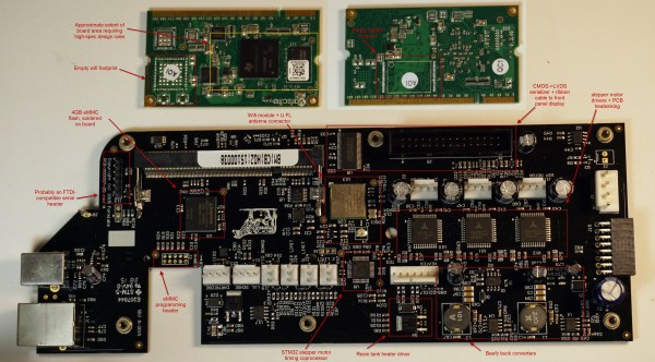
[Bunnie Huang] recently had the opportunity to do a thorough teardown of the new Formlabs Form 2 printer. It’s a long read, so just head over there and immerse yourself in every detail. If you want the cliff notes, though, read this but still go look at all the pretty pictures.
First, it’s a major upgrade with pretty much every component. The CPU is a huge step up, the interface went from monochrome to full color touch screen, the connectivity has been upgraded with WiFi and Ethernet, the optics are much better and safer, the power supply is integrated, there are lots of little improvements that handle things like bed leveling, calibration, resin stirring, pausing jobs, and resin refilling during a print. Bunnie practically gushes at all the features and impressive engineering that went into the Form 2.
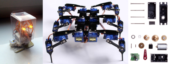
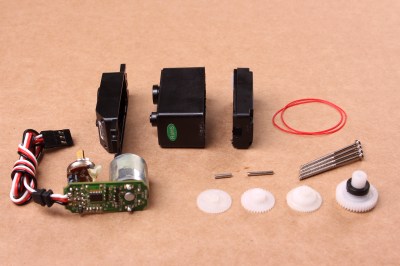
How do you make things move? You add in a motor that converts electrical energy into motion. That’s a simple idea, but how do you know where the motor is? That’s where the servo motor comes in. By adding a sensor and a controller to the mechanism, these motors can figure out how far they have rotated and maintain that setting without any need for external control.
A disassembled servo motor showing the controller, motor, rotary encoder and gears. By oomlout, CC BY-SA 2.0
What is a Servo Motor?
These neat devices can be large or small, but they all share the same basic characteristics: a motor connected to a gearing mechanism and an encoder that detects the movement and speed of the motor. This combination means that the controlling device doesn’t need to know anything about the motor itself: the controller on the servo motor handles the process of feeding the appropriate power to the motor until it reaches the requested position. This makes it much easier to build things with servomotors, as the designer has already done all the hard work for you.
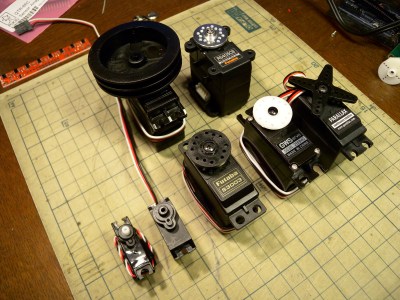
The first place that most people encounter a servo motor is in the small hobby servos that are used in remote control vehicles. Manufactured by companies like Hitec and Futaba, these drive a gear or arm that transfers the rotation of the motor to perform tasks like turning a wheel to steer a car, moving a control surface on an RC plane, or any task that requires a small range of motion at high precision. The gearing in the servomotor offers more torque than connecting the shaft directly to the motor. Most hobby servos of this type are restricted to a certain range of motion (usually 180 degrees) because the position encoder is a simple potentiometer connected to the output shaft.
A selection of different sized servo motors. By Osamu Iwasaki
Servomotors usually have three connection wires: a power line, a ground line and a signal line. The signal line is fed a pulse width modulation (PWM) signal that determines the angle that the servomotor moves to. As the name suggests, the length of the pulse (or the width, if you look at it on an oscilloscope) is the thing that controls the angle that the servo moves to: a short pulse (1 millisecond) sets it to the zero angle, while a long pulse of 2 milliseconds sets it to the maximum angle. A pulse length between these two limits signals the servomotor to move to the corresponding angle: 1.5 ms would set it to 90 degrees.
It is important to note that servomotors and stepper motors are not the same thing. Both are used for positioning, but steppers usually run without feedback. Instead, steppers turn (as the name suggest) in discrete steps. To figure out where a stepper motor is requires a limit switch, then driving the stepper until this is triggered. Then if you keep count out the number of steps that it’s traveled, you know where it is. That’s why devices like inkjet or 3D printers will move to their limits when they start up, so the controller can detect the far limit of the mechanism being driven, and calculate the current position from that.
How Do You Use A Servomotor?
Because the designers of servomotors have done most of the hard work for you, servomotors are very easy to use. To drive them, you just need to feed them power (usually 5V) and feed the PWM signal to the servomotor. You can drive them directly from an Arduino or similar microcontroller using a library that converts an angle into a PWM signal on one of the output pins.
Each servomotor requires a dedicated output pin if they are being driven this way, though, so if you are driving a lot of servomotors, a dedicated controller makes more sense. Devices such as the Adafruit Servo Shield and the Pololu Maestro allow you to control multiple servos from a single output pin on the microcontroller: the microcontroller sends a signal to the device addressing each servo in turn, and the device converts this into the PWM signals for each. If you need to drive a lot of servos, the SD84 can control up to 84 servos at once from a single USB port.
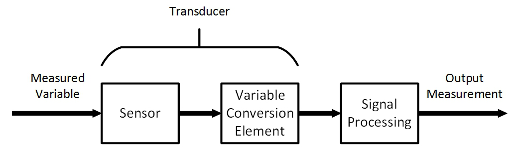
In the first article about measurement systems we looked at sensors as a way to bring data into a measurement system. I explained that a sensor measures physical quantities which are turned into a voltage with a variable conversion element such as a resistor bridge. There will always be noise in any system, and an operational amplifier (op-amp) can be used to remove some of that noise. The example we considered used an op-amp in a differential configuration that removes any disturbance signal that is common to both inputs of the op-amp.
But that single application of an op-amp is just skimming the surface of the process of bringing a real-world measurement of a physical quantity into a digital system. Often, you’ll need to do more work on the signal before it’s ready for sampling with a digital-to-analog converter. Signal conditioning with amplifiers is a deep and rich topic, so let me make it clear that that this article will not cover every aspect of designing and implementing a measurement system. Instead, I’m aiming to get you started without getting too technical and math-y. Let’s just relax and ponder amplifiers without getting lost in detail. Doesn’t that sound nice?
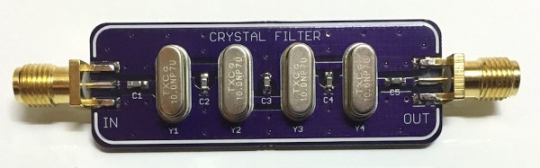
Most hobbyists use crystals as an external clock signal for a microcontroller. A less common use would be to make a bandpass filter (BPF) for an RF signal. [Dan Watson] explains his crystal ladder design on his blog and links to several sources for understanding the theory and creating your own crystal ladder band pass filter. If you want a set of these purple PCBs you can order them straight from the purple fab.
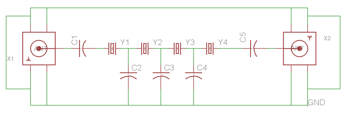
[Dan]’s schematicOne of the sources that [Dan] cites is [Larry Benko]’s personal site which is primarily dedicated to amateur radio projects. Which you can find much more in-depth information regarding the design of a xtal BPF. [Larry] goes into detail about the software he uses and some of the applications of crystal ladder filters.
BPF designed by [Larry]The process includes measuring individual xtals to determine which ones will work together for your target frequency. [Larry] also walks you through the software simulation process using LTSpice. If you aren’t familiar with Spice simulation you can get caught up by checking out the series of Spice articles by our very own [Al Williams].
The physical world is analog and if we want to interface with it using a digital device there are conversions that need to be made. To do this we use an Analog to Digital Converter (ADC) for translating real world analog quantities into digital values. But we can’t just dump any analog signal into the input of an ADC, we need this analog signal to be a measurable voltage that’s clean and conditioned. Meaning we’ve removed all the noise and converted the measured value into a usable voltage.
Things That Just Work.
This is not new information, least of all to Hackaday readers. The important bit is that we rely on these systems daily and they need to work as advertised. A simple example are the headlights in my car that I turned on the first night I got in it 5 years ago and haven’t turned off since. This is not a daytime running lights system, the controller turns the lights on when it’s dark and leaves them off during the day. This application falls into the category of things that go largely unnoticed because simply put: They. Work. Every. Time. It’s not a jaw dropping example but it’s a well implemented use of an analog to digital conversion that’s practical and reliable.
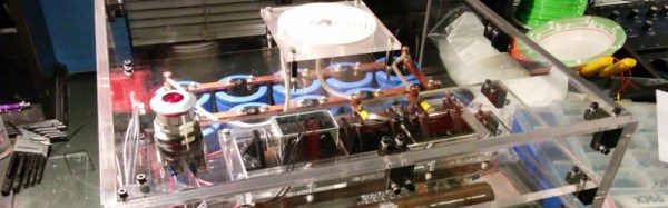
Project Hathor is an electromagnetic ring launcher that launches aluminium hard drive platters 45 feet skywards at the touch of a button. The hard work is done by a bank of capacitors which are charged to 2kV from a microwave oven transformer, before being discharged into a coil of wire on which the hard drive platter is sitting. The resulting burst of magnetic field induces a huge current in the platter, and that current in turn creates an opposing field which launches the ring into the air.
The launcher is the work of [Krux], at the Syn Shop hackerspace in Las Vegas, and he’s made a beautiful job of it. The capacitor bank has ten 3900uF 400V electrolytic capacitors wired as a single 1560uF 2kV capacitor, there are two 225W 2Kohm wire wound discharge resistors, and a beautifully designed home-made high voltage contactor featuring tungsten electrodes. The whole project has been carefully built into an acrylic case for safety, for as [Krux] points out, microwave oven transformers will kill you.
As well as the project web site, there is a YouTube playlist, an image gallery, and a GitHub repository containing all the project’s details. You can see the launcher in action in the video below, launching platters into the Nevada night right on cue.


![BPF designed by [Larry]](https://hackaday.com/wp-content/uploads/2016/03/20m_xtalbp_s21close_7-23-2009.gif)