A Simple LED Flashlight Composed Of A Relay And A Magnet

In our tips line we sometimes receive hacks that are amazing just because of their ingenuity. This relay-powered flashlight is definitely one of them. It has been named RattleGen by its creator [Berto], who apparently often makes simple hacks used in his everyday life (have a look at his YouTube channel).

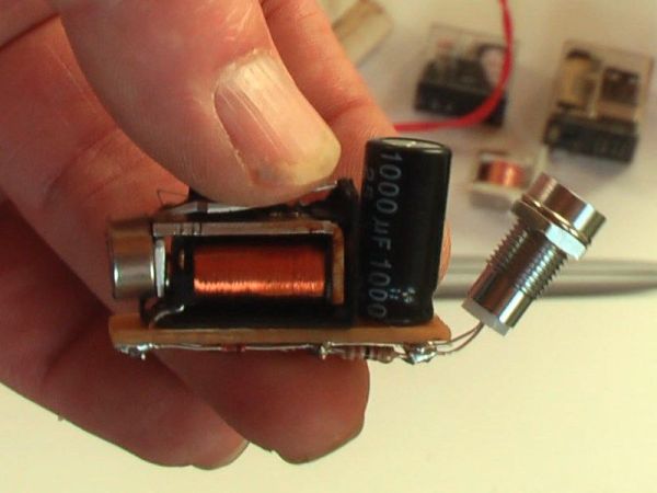
To understand this hack, you first need to know (in case you didn’t already) that a magnet moving near a conductor (here a coil) induces a voltage at its terminals. This is called electromagnetic induction. In the picture you see above, you may distinguish a disassembled relay with a magnet located on the lever’s end. As a ferromagnetic metal is already placed inside the coil, the lever is by default ‘stuck’ in this position. By continuously pressing the latter on its other end, important voltage spikes are created at the coils terminals. [Berto] therefore used a bridge rectifier to transform the AC into DC, and a 1000uF capacitor to smooth the power sent to his super bright LED. A video of the system in action is embedded after the break.

Continue reading “A Simple LED Flashlight Composed Of A Relay And A Magnet”

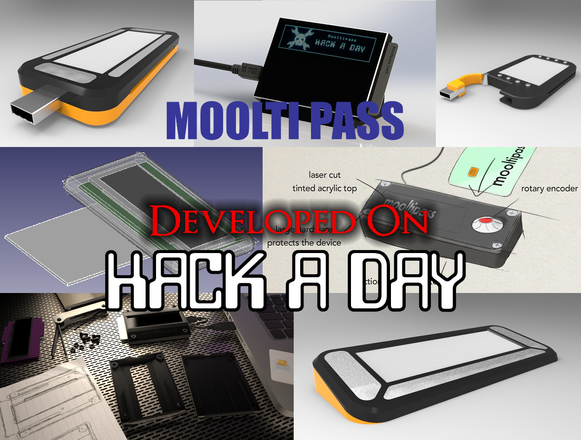
Developed On Hackaday: We Have Pixels!

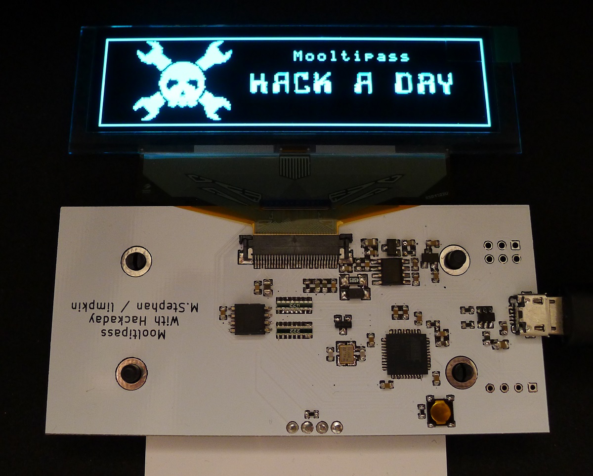
It has been a while since we kept you informed about the current state of the Mooltipass project. Well, several days ago we finally received the PCBs we got produced at Seeedstudio. Keep in mind that this first version (shown in the picture above) is only meant to check that the chosen components can suit our needs while our mechanical contributors work on their designs. Moreover, we may add empty footprints for our readers that may want to hack the device.

After a few hours of soldering and a few days of coding, we finally got a basic firmware running. The OLED screen is easily readable and has an amazing contrast (the picture doesn’t do it justice). So far we checked all basic functionalities of the on-board components and it’ll still take a few days/weeks to be certain that we can settle with them. We are therefore starting to ship a few platforms to the firmware developers that want to work on the core functions of the Mooltipass. So if you’re an experienced C developer and have some spare time, you may get onboard by contacting me at mathieu[at]hackaday[dot]com or by joining the Mooltipass Google Group.

In a few days we will publish the designs that our mechanical guys came up with and we’ll ask you to let us know which ones are your favorites. Depending on how things will go, we may produce PCBs for several of them to select our final design based on user experience and ease of use. We look forward to hearing your feedback in the comments section below!

[Bunnie]’s Open Source Laptop Is Ready For Production

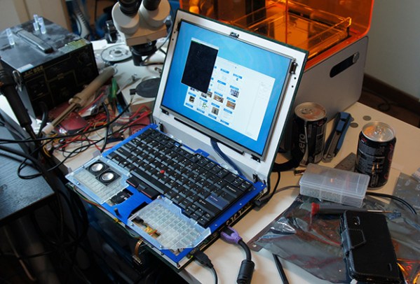
Just over a year ago, [Bunnie Huang] announced he was working on a very ambitious personal project: a completely open source laptop. Now, with help from his hardware hacker compatriot [xobs], this laptop named Novena is nearly complete.

Before setting out on this project, [Bunnie] had some must-have requirements for the design. Most importantly, all the components should be free of NDA encumbrances. This isn’t an easy task; an SoC vendor with documentation sitting around on their servers is rare as hen’s teeth, and Freescale was the only vendor that fit the bill. Secondly, the entire laptop should be entirely open source. [Bunnie] wasn’t able to find an open source GPU, so using hardware video decoding on his laptop requires a binary blob. Software decoding works just fine, though.

Furthermore, this laptop is designed for both security and hardware hacking. Two Ethernet ports (one 1Gbit and the second 100Mbit), a USB OTG port, and a Spartan 6 FPGA put this laptop in a class all by itself. The main board includes 8x analog inputs, 8x digital I/O ports, 8 PWM pins, and a Raspberry Pi-compatible header for some real hardware hackery.

As for the specs of the laptop, they’re respectable for a high-end tablet.  The CPU is a Freescale iMX6, a quad-core ARM Cortex-A9 running at 1.2 GHz. The RAM is upgradeable to 4GB, an internal SATA-II port will easily accommodate a huge SSD, the ability to use an LCD adapter board to run the 13-inch 2560×1700 LED panel [Bunnie] is using. The power system is intended to be modular, with batteries provided by run-of-the-mill RC Lipo packs. For complete specs, check out the wiki.

Despite the high price and relatively low performance (compared to i7 laptop) of [Bunnie]’s laptop, there has been a lot of interest in spinning a few thousand boards and sending them off to be pick and placed. There’s going to be a crowd funding campaign for Novena sometime in late February or March based around an “all-in-one PC with a battery” form factor. There’s no exact figure on what the price of a Novena will be, but it goes without saying a lot will be sold regardless.

If you want the latest updates, the best place to go would be the official Novena twitter: @novenakosagi

Rex, The ARM-Powered Robot Board

REX

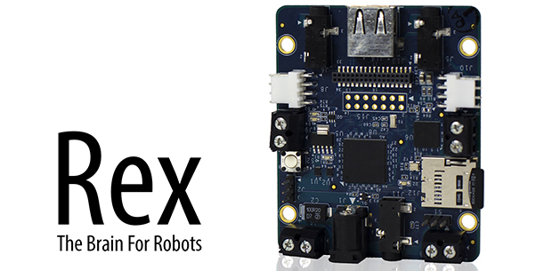
There are a million tutorials out there for building a robot with an Arduino or Raspberry Pi, but they all suffer from the same problem: neither the ‘duino nor the Raspi are fully integrated solutions that put all the hardware – battery connectors, I/O ports, and everything else on the same board. That’s the problem Rex, an ARM-powered robot controller, solves.

The specs for Rex include a 1GHz ARM Cortex-A8 with a Video SoC and DSP core, 512 MB of RAM, USB host port, support for a camera module, and 3.5mm jacks for stereo in and out. On top of that, there’s I2C expansion ports for a servo adapter and an input and output for a 6-12 V battery. Basically, the Rex is something akin to the Beaglebone Black with the hardware optimized for a robotic control system.

Because shipping an ARM board without any software would be rather dull, the guys behind Rex came up with Alphalem OS, a Linux distro that includes scripts, sample programs, and an API for interaction with I2C devices. Of course Rex will also run other robotics operating systems and the usual Debian/Ubuntu/Whathaveu distros.

It’s an impressive bit of hardware, capable of speech recognition, and machine vision tasks with OpenCV. Combine this with a whole bunch of servos, and Rex can easily become the brains of a nightmarish hexapod robot that responds to your voice and follows you around the room.

You can pick up a Rex over on the Kickstarter with delivery due sometime this summer.

Testing The Limits Of Home PCB Etching

[Quinn Dunki]’s Veronica, a homebrew computer based on the 6502 CPU, is coming along quite nicely. She’s just finished the input board that gives Veronica inputs for a keyboard and two old Nintendo gamepads. [Quinn] is building this computer all by her lonesome, including etching all the PCBs. She’s gotten very, very good at etching her own boards, but this input board did inspire a few facepalming moments.

In an earlier post, [Quinn] went over her PCB etching capabilities. As demonstrated by the pic above, she’s able to print 16 mil traces with 5 mil separation. This is just about as good as you can get with homebrew PCBs, but it’s not without its problems.

[Quinn] is using a photographic process for her boards where two copies of a mask is printed on an acetate sheet, doubled up, and laid down on a pre-sensitized copper board. The requirement for two layers of toner was found by experience – with only one layer of toner blocking UV light, [Quinn] got some terrible pitting on her traces and ground planes.

Two photographic masks means the masks must be precisely aligned. This example shows what happens when the acetate sheets are ever so slightly misaligned. With a 5 mil gap between traces, [Quinn] needs to align the masks to within ±2.5 mils; difficult to do by eye, and very hard once you factor in flexing and clamping them down to the copper board.

Even when this process goes perfectly, [Quinn] is pushing the limits of a laser printer. When printing at 600 dpi, the pixels of the print are about 1.5 mils. While GIMP, printer drivers, and the printer itself have some fancy software to help with the interpolation, [Quinn] is still seeing ‘bumps’ on the edges of perfectly aligned parts. This is one of those things that really makes you step back and realize how amazing fabbing PCBs at home actually is.

With most of the hardware for Veronica out of the way, it’s just about time for [Quinn] to start programming her baby. We’re not expecting a full-blown operating system and compiler, but those NES gamepads are probably crying out for some use.

Interfacing With The HTC Desire Display And Its Touch Panel

Part of [Linas]’ submission to last year’s Cypress Smarter Life Challenge involved using the HTC Desire display and its touch screen. This particular phone includes a full-color active-matrix OLED (AMOLED) display that has a 3.7″ diagonal and a 480×800 resolution, resulting in a 252ppi pixel density. Using a MSO2024B oscilloscope, [Linas] originally started his adventure with the touchscreen by sniffing the I2C signals. As some math was required to extract the data, he later found the HTC Desire source code and included it on his STM32F429 (so much for reverse engineering!).

After spending many hours searching for the AMOLED display and controller datasheets, [Linas] resorted to pay a company to get the resources he needed. He produced a custom-made PCB to provide the display with the required voltages, as well as offering a 0.1″ connector to interface with it. A RGB565 interface is used to communicate with the screen so only 65k out of the 16 million colors are used. You may download all the program files and datasheets in [Linas] write-up.

A Low Cost Dual Discriminator Module For The Easy-phi Project

A few months ago I presented you the Easy-phi project, which aims at building a simple, cheap but intelligent rack-based open hardware/software platform for hobbyists. With easy-phi, you simply have a rack to which you add cards (like the one shown above) that perform the functions you want.

Recently my team finished testing our FPGA-based discriminator or “universal input” if you prefer. As easy-phi cards use a well-defined electrical signal to communicate with each other, we needed to make a card that would translate the different kinds of electrical signals from the outside, as well as perform plenty of other functions. It was therefore designed to have a 100MHz input bandwidth with an AC/DC coupled 50 ohm/high impedance input stage (x2) and 4 easy-phi outputs. For this module, we picked the (old) spartan3-an FPGA to perform the different logic functions that may be needed by the final users (high speed counter, OR/XOR/AND, pulse creation,…). Using the cortex-m3 microcontroller present on the board, it may be easily reconfigured at will. All design resources may be found on our Github, and you can always have a look at our official website.