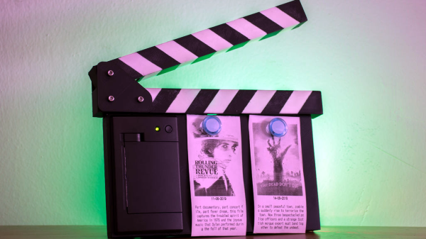
The clapperboard is a device used in video to synchronize audio and video. Its role in movies is well known and its use goes back in one form or another to the 1920s. [Gocivici] is a big movie fan and created a clapperboard that is able to print out posters of recently announced movies when the clapper is clapped.
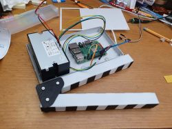
The poster is not a big, full color job, but rather a black and white one, roughly the size of a movie ticket. [Gocivici] keeps his movie tickets in a journal and wanted to be able to keep small posters in there along with them. A thermal printer is used to print the poster along with the title, the release date, and some information about the movie. In addition to the printer, the hardware involved is a Raspberry Pi, a switch, and an LED. The clapperboard itself is 3d printed and then painted. A bit of metal is used to keep the clappers apart and give a bit of resistance when pressing them together. A nice touch is a metal front, so you can use magnets to keep your posters on the board.
[Gocivici] has detailed build instructions up along with a video (available after the break) showing the printer in action. The 3d models are available as well as the code used to create the posters after grabbing data from TMDb. If you need your clapperboard to be as accurate as possible, take a look at this atomic clock clapperboard.
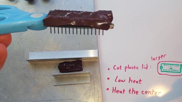
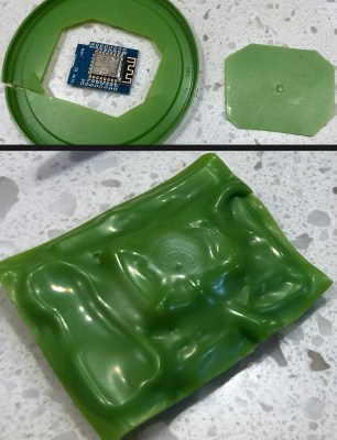 your magic smoke. Even if you are lucky, stray parts are the root of boundless malfunctions from disruptive to deadly. [TheRainHarvester] shares his trick for
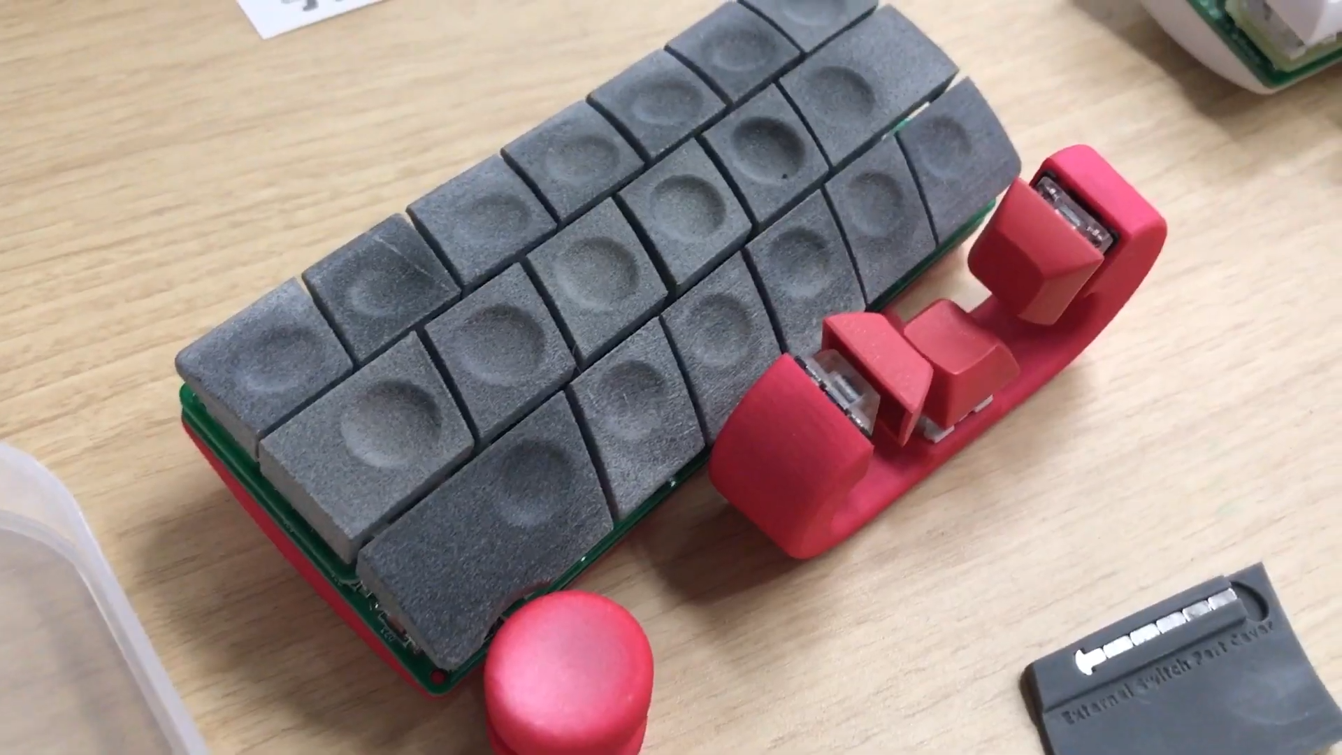
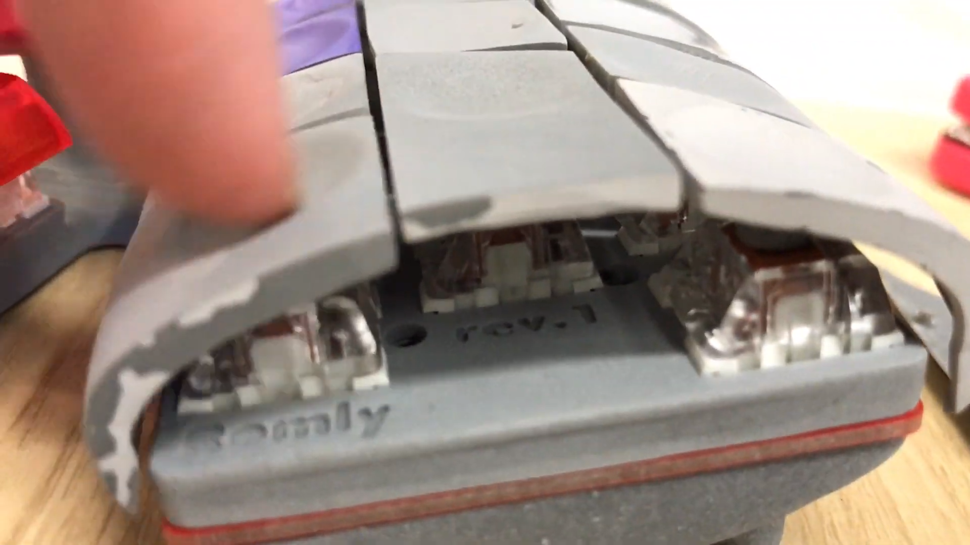 Speaking of [romly], one of their designs stands out as particularly unusual. There are a few things to note here. One is the very conspicuous
 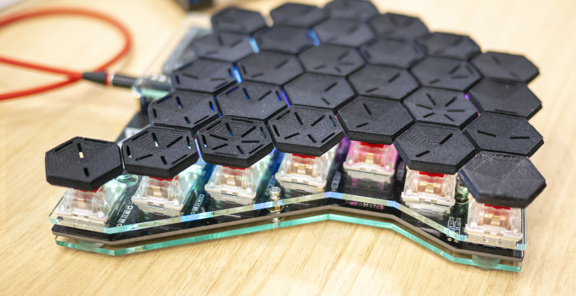 Another interesting entrant is this keyboard with unusually staggered switches and hexagonal caps (check out the individual markings!). Very broadly there are two typical keyboard layout styles; the diagonal columns of QWERTY (derived from a typewriter in the 1800’s) or the non slanted columns of an “