[Hesam Moshiri] has built a variable switch-mode power supply over on hackaday.io. When prototyping a new circuit, often the goal is to get a proof-of-concept working as soon as possible to iron out all of the bugs it might have. The power supply can easily be an afterthought, and for smaller projects we might just reach for an adjustable LM317 voltage regulator to dial in the correct voltage and then move on with the meat of the project. These linear regulators are incredibly inefficient though, so if you find yourself prototyping with one of these often enough, it might be worthwhile to switch to something better.
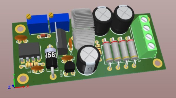
While it’s easy to simply buy a switch-mode power supply (SMPS) that has everything you need, and rated for 90% or higher efficiency at the same time, getting one with an adjustable output isn’t as easy. This one is based on the relatively popular LM2576-Adj chip which handles the switching frequency part of the circuit automatically. You will also need some large capacitors, an inductor (one of the disadvantages of an SMPS circuit) and a small potentiometer to use as the feedback control for the LM2576. This special pin allows the output voltage of the SMPS to be precisely controlled.
Granted, this project might not be breaking any new grounds, but if you’ve never given serious thought to your small breadboard circuit power supplies, it’s definitely worth looking into. An improvement from a linear regulator’s 30% efficiency to 90% efficiency from an SMPS will not only save you a ton of energy but also solve a lot of heat dissipation problems. If you don’t want to build a switch-mode supply 100% from scratch, though, it might also be possible to modify an existing one to suit your needs as well.