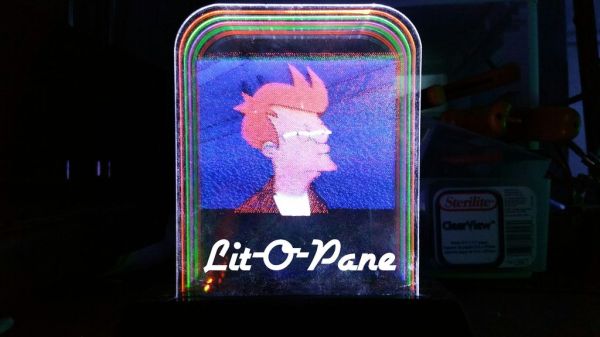
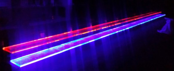
Edge-lit art has been around for a very long time, and most people have probably come across it in a gift shop somewhere. All it takes is a pane of transparent material (usually an acrylic sheet) with the artwork etched into the surface. Shine a light into the sheet from the edge, and refraction takes over to light up the artwork. However, this technique is almost always limited to a single pane, and therefore a single color. [haqnmaq] wanted to take this idea and make it full-color, and has written up a great Instructables tutorial on how to accomplish this.
If you want to make something like this yourself, the only thing you really need is a laser cutter and some basic electronics equipment. The process itself is so straightforward that it’s surprising that it isn’t more common. You start by taking a photo of your choice and use an image editor to break it up into three photos, one for red, one for green, and one for blue. Each of those photos is then etched into an acrylic pane with a laser cutter. When the panes are positioned in front of each other and edge-lit with their respective LEDs, a full-color image comes to life.
This isn’t the first edge-lit artwork project we’ve featured, but it definitely has the highest fidelity. Because [haqnmaq’s] technique uses three colors, you can use his tutorial to reproduce any photo you like. You could even take this a step further and create animated photos by adding more panes and lighting them up in the correct sequence!
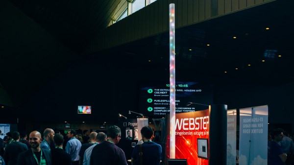
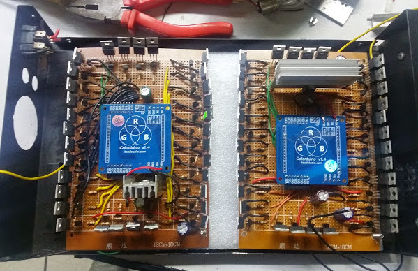 The project took around 450 meters of RGB strips controlled by