There’s no doubt that the 7-segment display is a gold standard for displaying lighted digits. But what about a throwback to an older system of displaying numbers — Cistercian? With thirty-one 0805 LEDs, [Josue Alejandro] made a simple module displaying a single Cistercian digit (any from 0-9999).
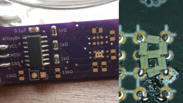
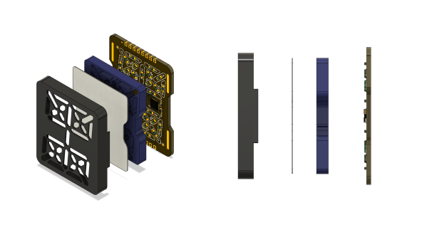
The first iteration used castellated edges and required a significant number of GPIO, so on the next rev, he switched to a serial-to-parallel converted from Lumissil (IS31FL3726A). A diffuser and spacer were printed from PLA and made for an incredibly snazzy-looking package.
Of course, it couldn’t stop there, and a third revision was made that uses SK6812 Neopixels, allowing full RGB capability. All the design documents, layout files, and incredibly detailed drawings are available on GitHub. What makes this incredibly handy is having a module you can easily add to a project. Perhaps even as a component in an escape room in a box that would allow you to flash multiple numbers. Or perhaps as a stylish clock. We’d even go so far as to challenge someone to create a calculator by combining several of these modules with this keypad.