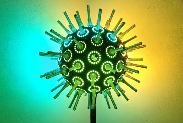
Any resemblance between The Wobble Sphere and a certain virus making the rounds these days is purely coincidental. Although as yet another project undertaken during the COVID-19 lockdowns, we can see where the inspiration came from.
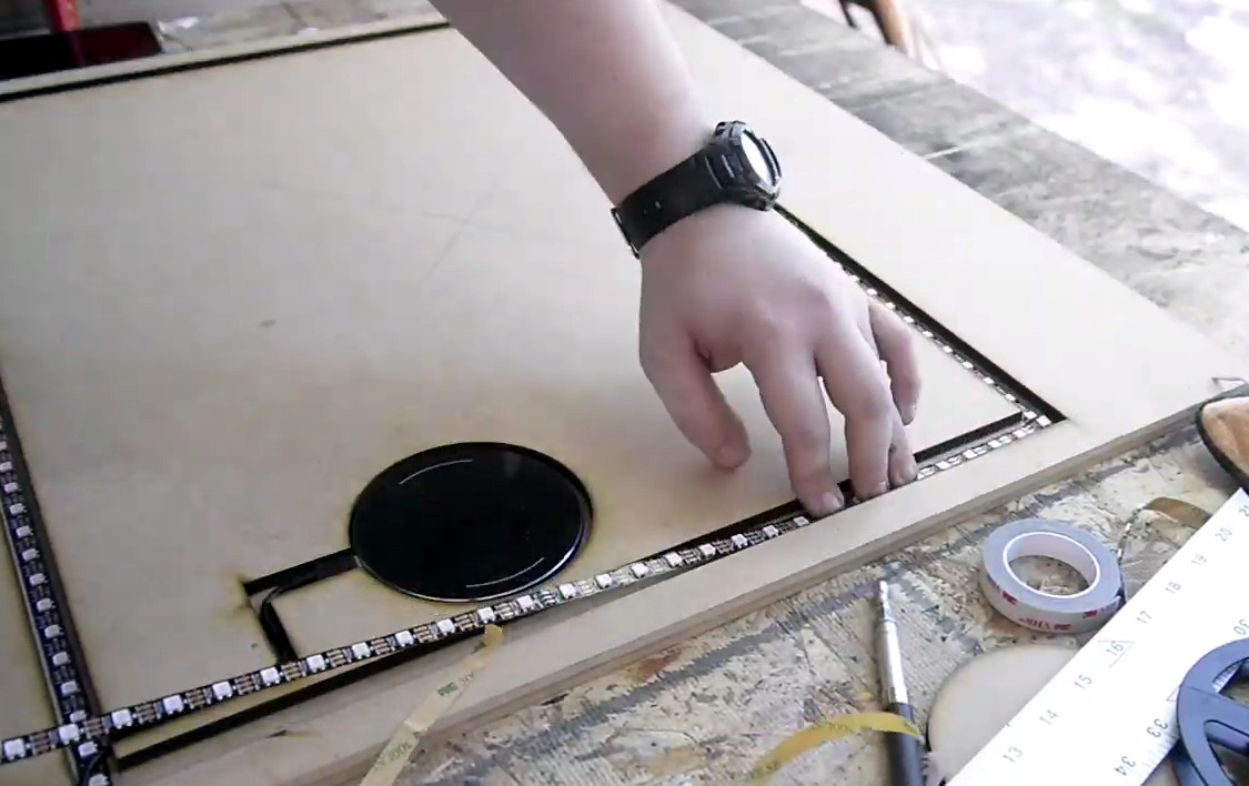
Wobble Sphere is another work of interactive art from the apparently spring-driven imagination of [Robin Baumgarten], whose Quantum Garden piece graced our pages last year. The earlier, flatter version used a collection of spring door stops — the kind that sound awesome when plucked by a passing foot — each of which is surrounded by a Neopixel ring. The springs act as touch sensors that change the patterns and colors on the LED rings in endlessly fascinating ways.
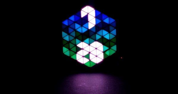
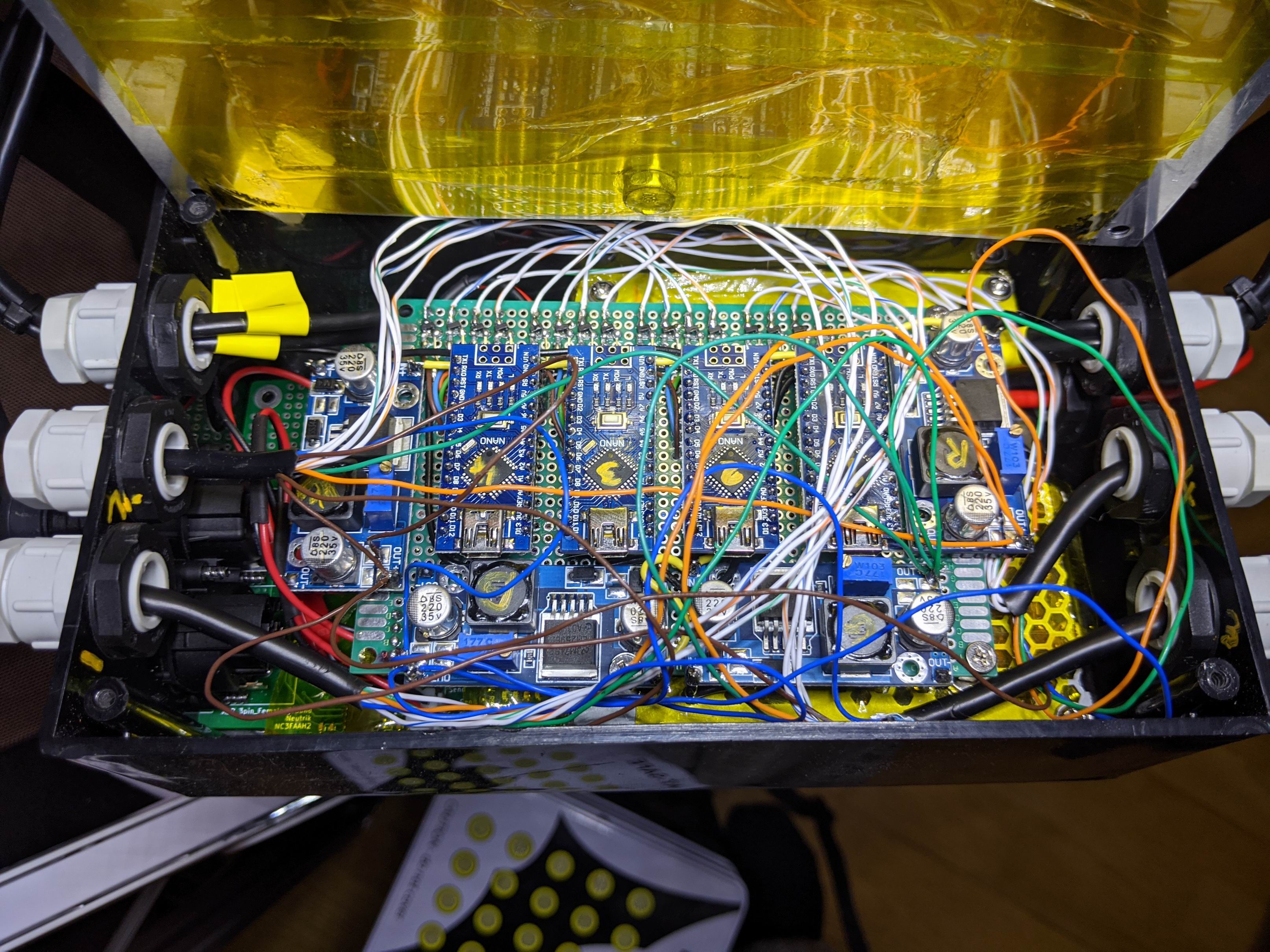
For Wobble Sphere, [Robin] took the same spring and LED units, broke them into a collection of hexagonal and pentagonal PCBs, and wrapped the whole thing up into a 72-sided polyhedron. There’s some impressive mechanical and electrical engineering involved in the transition from 2D to 3D space, not least of which is solving the problem of how to connect everything while providing pluck-friendly structural support. The former was accomplished with a ton of ribbon cables, while the latter was taken care of with a combination of a 3D-printed skeleton and solder connections between adjacent PCBs. The result is a display that invites touch and rewards it with beautiful patterns of light chasing around the sphere. See it in action in the video after the break.
Lest anyone think springs are the only tool in [Robin]’s box, we mustn’t forget that he once set a knife-wielding Arduino-powered game on an unsuspecting public. Check it out; it’s way more fun than it sounds.
Continue reading “Springs And Things Wrap Into A Polyhedron Of Interactive LED Art”