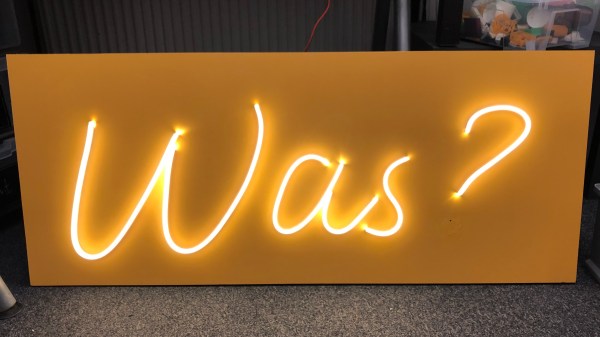
To a speaker of English, a sign asking ‘Was?” may not make much sense. In German, however, the question is a more thought-provoking “What?” That’s exactly the point of this faux-neon sign created by [noniq]. The sign uses silicone-enclosed “neon-like” LED strips to spell out the question for all to see — and ponder.
While true neon aficionados will bristle at even calling such LED strips “faux neon” (check the comments below for examples), we really like them for sign projects like this. They’re great-looking, inexpensive, easy to work with, and available with RGB LEDs for variable colors. In this case, they were mounted on 3 mm polystyrene plate glued to a wooden frame made from 22 mm square beams.
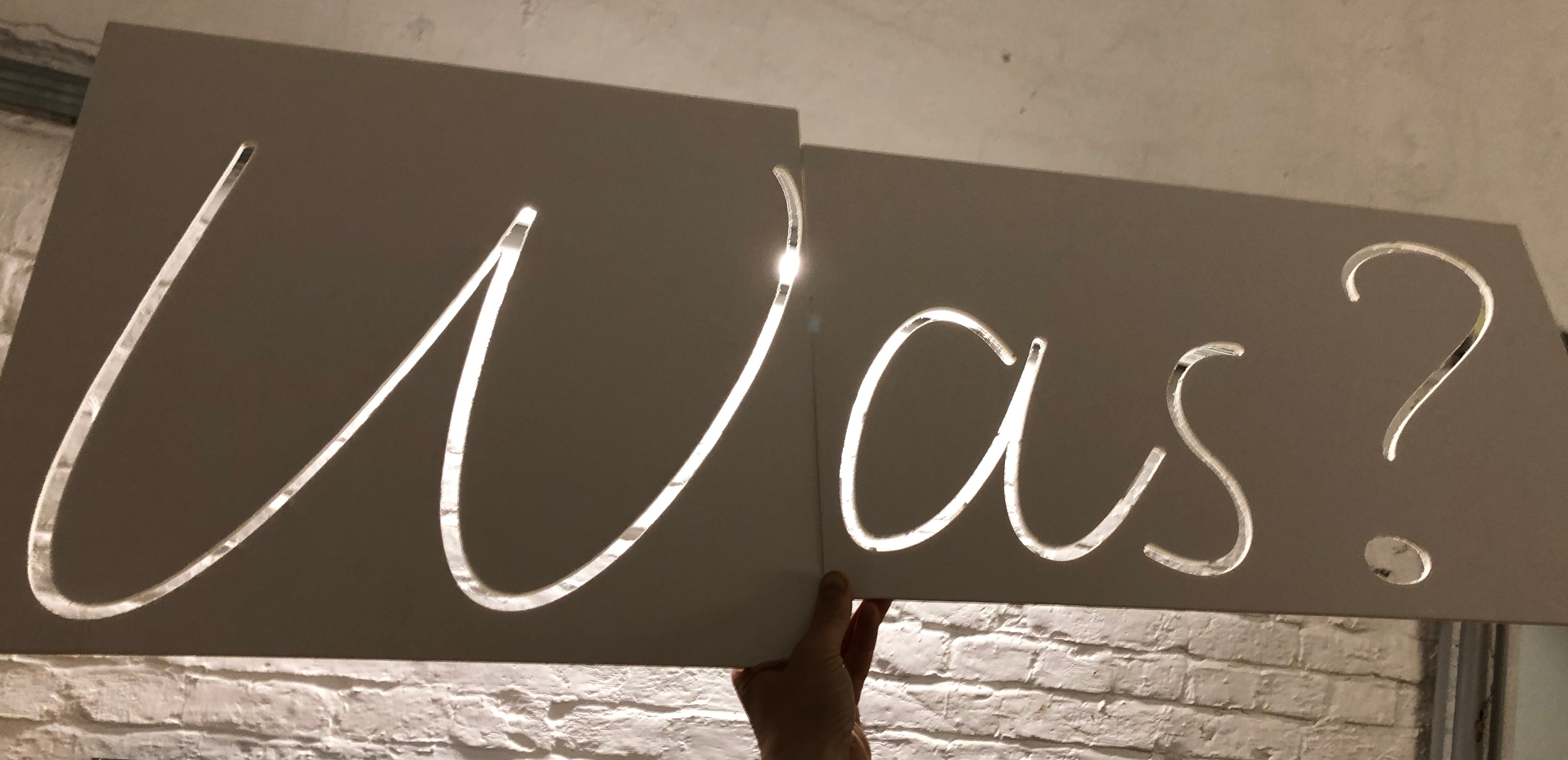 One of the things that caught our eye about this build is the use of a CNC mill to create a prototype. With the strokes milled out of a foam board, the final effect could be visualized before committing to the design. This board later served as a template for cutting the LED strips to length — clever! We suspect this could also be done with a hobby knife and a liberal dose of patience by those without access to a CNC mill.
Of course, this type of project doesn’t always turn out perfect the first time. The sign was missing a dot for the question mark, light leakage from ends of the individual segments was creating distracting bright spots on the base, areas where the silicone had been removed to connect the LEDs were noticeably darker, and the letters looked too thin. We’re looking forward to the promised second post, in which [noniq] describes the solution to these issues.
This isn’t the first time we’ve seen these LED strips used for sign-making, like in this logo build last Spring.

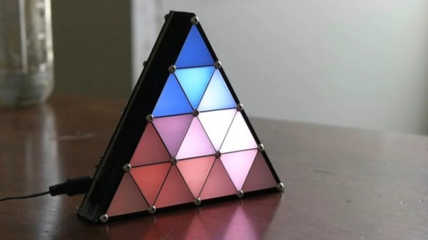
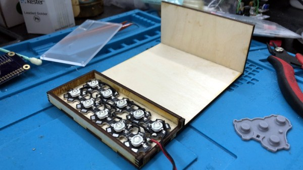
 Hailing from the recent past of 2014, it’s a design that is well-suited to the average makerspace. Built out of layers of lasercut chipboard and acrylic, it creates 16 seperate pockets for LEDs with very little bleed in between. A black bezel is fitted to complete the effect, along with frosted white acrylic diffusers for each triangle element.