Moving Forth With Mecrisp-Stellaris And Embello

In the last episode, I advocated a little bit for Forth on microcontrollers being a still-viable development platform, not just for industry where it’s usually seen these days, but also for hackers. I maybe even tricked you into buying a couple pieces of cheap hardware. This time around, we’re going to get the Forth system set up on that hardware, and run the compulsory “hello world” and LED blinky. But then we’ll also take a dip into one of the features that make Forth very neat on microcontrollers: easy multitasking.

To work!

Hardware

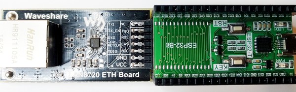
Mecrisp-Stellaris Forth runs on a great number of ARM microcontrollers, but I’ll focus here on the STM32F103 chips that are available for incredibly little money in the form of a generic copy of the Maple Mini, often called a “STM32F103 Minimum System Board” or “Blue Pill” because of the form-factor, and the fact that there used to be red ones for sale. The microcontroller on board can run at 72 MHz, has 20 kB of RAM and either 64 or 128 kB of flash. It has plenty of pins, the digital-only ones are 5 V tolerant, and it has all the usual microcontroller peripherals. It’s not the most power-efficient, and it doesn’t have a floating-point unit or a DAC, but it’s a rugged old design that’s available for much less money than it should be.

Programmer Connected, Power over USB

Similar wonders of mass production work for the programmer that you’ll need to initially flash the chip. Any of the clones of the ST-Link v2 will work just fine. (Ironically enough, the hardware inside the programmer is almost identical to the target.) Finally, since Forth runs as in interactive shell, you’re going to need a serial connection to the STM32 board. That probably means a USB/serial adapter.

This whole setup isn’t going to cost much more than a fast food meal, and the programmer and USB/serial adapter are things that you’ll want to have in your kit anyway, if you don’t already.

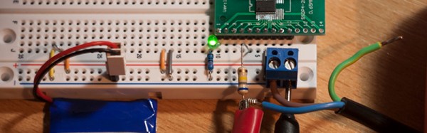
You can power the board directly through the various 3.3 and GND pins scattered around the board, or through the micro USB port or the 5V pins on the target board. The latter two options pass through a 3.3 V regulator before joining up with the 3.3 pins. All of the pins are interconnected, so it’s best if you only use one power supply at a time.

Continue reading “Moving Forth With Mecrisp-Stellaris And Embello”

Enabling Ethernet On The ESP32

The ESP32 is the latest and greatest wonderchip from Espressif. It’s a 32-bit, dual-core chip with WiFi, Bluetooth, and tons of peripherals such as CAN and Ethernet. For most of these peripherals, Espressif already has a few bits of example code, but [Frank Sautter] didn’t like the Ethernet implementation. The ‘stock’ code calls for a TLK110 Ethernet PHY, but that’s an expensive chip when bought in quantity one. A better chip would be the LAN8720, so [Frank] built a board to enable Ethernet on the ESP32 with this chip.

The ESP32 only needs a few components to wire it into an Ethernet network. Just a few resistors, capacitors, and an RJ45 jack will take care of most of the work, but because he’s taking the Ethernet ‘shield’ route, he needs to add his own Ethernet PHY. The Waveshare LAN8720 is the chip for this, but there’s an issue with the pin configuration of the ESP32. GPIO0 on the ESP32 has two functions — the first is pulling it low during startup for serial programming, and the second is the clock input for the EMAC function block. Some bit of circuitry must be devised to allow for both conditions to enable Ethernet on the ESP32.

[Frank]’s solution is to add a few pull-up and pull-down resistors to a breakout board, and use an unused GPIO pin to switch GPIO0 high during startup, but allows a crystal to grab it a bit later. It’s a hack, certainly, but it does allow for some much cheaper chips to be used to give the ESP32 Ethernet.

Mains Clocking A Microcontroller

[Lujji] is playing around with the STM8 microcontroller. In reviewing the official documentation for this chip, he read the external clock can be a sine wave, a triangle wave, or a square wave with a 50% duty cycle. The minimum CPU frequency is 0 Hz. [Lujji] doesn’t have a signal generator, and presumably, he’s all out of crystals. He does have mains AC, though, so why not clock a microcontroller with wall power?

Using mains power as a frequency standard is a concept a hundred years old. Synchronous motors turn at a rate proportional to the mains frequency, and this has been used in clocks for decades. If you’re really clever, you can clock digital circuits with mains AC, but we’ve never seen someone replace a tiny crystal in a microcontroller circuit with mains power.

After an experiment to prove the concept, [Lujji] went on to construct a circuit that wasn’t as dumb as connecting the microcontroller directly to a wall socket. The direct approach didn’t work that well anyway — the STM8 didn’t like low frequency clocks with slow edges. [Lujji] needed a clock with cleaner edges, and a 555 configured as a comparator fit the bill.

The completed circuit sends mains power through an optocoupler to drive a 555 configured as a comparator. The output is a clean 50Hz clock that is connected to the OSCIN pin on an STM8. This is now a chip running at 50Hz, and yes, it works. [Lujji] set up a circuit to write ‘Hello World’ on an old Nokia LCD. That took about three minutes. It works, though, even though it’s completely useless. Maybe this can be applied to some novel timekeeping similar to that one-instruction-per-day clock we looked earlier in the year.

8-Bit Breadboard Computer Is Up To 8 Hours

[Ben Eater] posted some videos of an 8-bit computer with no CPU chip that he built completely on a breadboard a few years ago. After being asked for schematics, he finally admitted that he didn’t have any. So, instead, he decided to rebuild it and keep a video log of each step in the process. You can see his kickoff video, below, but you can also find 30 more recent videos covering topics from the ALU design and troubleshooting to the decimal LED display. He even uses an Arduino to program a EEPROM that he uses to replace a lot of logic.

You probably want to wait until you have some free time as there are around eight hours of videos so far. The videos start off with a simple 555 timer and work up from there. Each piece gets a test separate from the whole, so with luck you won’t have an impossible job trying to troubleshoot the whole thing at the end.

Continue reading “8-Bit Breadboard Computer Is Up To 8 Hours”

FreeRTOS Gets Class

[Michael Becker] has been using FreeRTOS for about seven years. He decided to start adding some features and has a very interesting C++ class wrapper for the OS available.

Real Time Operating Systems (RTOS) add functionality for single-thread microcontrollers to run multiple programs at the same time without threatening the firmware developer’s sanity. This project adds C++ to the rest of the FreeRTOS benefits. We know that people have strong feelings one way or the other about using C++ in embedded systems. However, as the 24 demo projects illustrate, it is possible.

One nice thing about the library is that it is carefully documented. A large number of examples don’t hurt either. The library is clean with just under 30 classes. It seems to have resisted the trend of having classes for everything. You know the kind of library we mean. To create an Integer object, just build a configuration object to pass to the class factory generator which…. This library doesn’t entertain any of that. It has simple abstractions around threads and timers, queues, and mutexes.

Continue reading “FreeRTOS Gets Class”

Everyone Loves Faster ESP8266 TFT Libs

Reader [Jasper] writes in with glowing praise for the TFT_eSPI library for the ESP8266 and the various cheap 480×320 TFT displays (ILI9341, ILI9163, ST7735, S6D02A1, etc.) that support SPI mode. It’s a drop-in replacement for the Adafruit GFX and driver libraries, so you don’t need to rework your code to take advantage of it. If you’re looking to drive an LCD screen with an ESP8266 and Arduino, check this out for sure.

As a testbed, [Jasper] ported his Tick Tock Timer project over to the new library. He got a sevenfold increase in draw speed, going from 500 ms to 76 ms. That’s the difference between a refresh that’s visibly slow, and one that looks like it happens instantly. Sweet.

Improving software infrastructure isn’t one of the sexiest or most visible hacks, but it can touch the lives of many hackers. How many projects have we featured with an ESP8266 and a screen? Thanks, [Bodmer] for the good work, and [Jasper] for bringing it to our attention.

Boost Converter Functionality At Rock-Bottom Prices

Linear voltage regulators are pretty easy to throw into a project if something in it needs a specific voltage that’s lower than the supply. If it needs a higher voltage, it’s almost just as easy to grab a boost converter of some sort to satisfy the power requirements. But if you’re on a mission to save some money for a large production run, or you just like the challenge of building something as simply as possible, there are ways of getting voltages greater than the supply voltage without using anything as non-minimalistic as a boost converter. [Josh] shows us exactly how this can be done using a circuit known as a charge pump to drive a blue LED.

One of the cool things about AVR microcontrollers is that they can run easily on a coin cell battery and source enough current to drive LEDs directly from the output pins. Obviously enough, if the LED voltage is greater than the voltage of the power supply, this won’t work. That is, unless you have a spare diode and capacitor around to build a charge pump.

The negative charge pump works by charging up a capacitor that is connected to an AVR pin, with the other side between the LED and a garden-variety diode to ground. That results in a roughly (VCC – 0.7) volt difference across the capacitor’s plates. When the AVR pin goes low, the other side of the capacitor goes negative by this same amount, and this makes the voltage across the LED high enough to light up. Not only is this simpler than a boost converter, but it doesn’t need any bulky inductors to work properly.

Will this work for any load? Am I going to start any fires by overdriving the LED? Luckily, [josh] answers all of these questions and more on the project page, and goes into some detail on the circuit theory as well. Granted, the charge pump doesn’t have the fine control over the power supply that you can get out of a buck or boost converter (or any switch-mode power supply). But it does have good bang-for-the-buck.