These days, when most folks think of a computer they imagine a machine with multiple CPUs, several gigabytes of RAM, and a few terabytes of non-volatile storage for good measure. With such modern expectations, it can be difficult to see something like a microcontroller as little more than a toy. But if said MCU has a keyboard, is hooked up to a display, and lets you run basic productivity and development software, doesn’t that qualify it as a computer? It certainly would have in the 1980s.
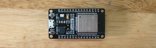
With that in mind, [Olimex] has teased the RVPC, which they’re calling the “world lowest cost Open Source Hardware All-in-one educational RISC-V computer” (say that three times fast). The tiny board features the SOIC-8 variant of the CH32V003 and…well, not a whole lot else. You’ve got a handful of passives, a buzzer, an LED, and the connectors for a PS/2 keyboard, a power supply, and a VGA display. The idea is to offer this as a beginner’s soldering kit in the future, so most most of the components are through-hole.
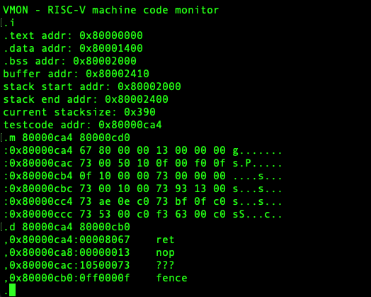 On the software side, the post references things like the ch32v003fun development stack, and the PicoRVD programmer as examples of open source tools that can get your CH32V computer up and running. There’s even a selection of retro-style games out there that would be playable on the platform. But what [Olimex] really has their eye on is a port of VMON, a RISC-V monitor program.
When paired with the 320×200 VGA text mode that they figure the hardware is capable of, you’ve got yourself the makings of an educational tool that would be great for learning assembly and playing around with bare metal programming.
It might not have the timeless style of the Voja4, but at least you can fit it in a normal sized pocket.
Thanks to [PPJ] for the tip.