Building A Home Automation Mesh Network

[Ian Harris] designed a bunch of home automation for his parents using X10 hardware. He was a bit disappointed by the failure rate of the modules and the overall performance of the system so he set out to replace it with his own hardware. Lucky for use he’s documented the journey in a four-part series about mesh networks.

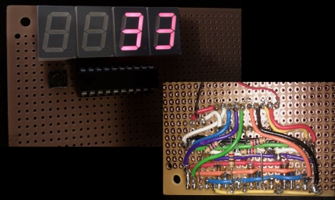
The hardware seen above is his test rig. He’s using a couple of Sparkfun breakout boards to develop for nrf2401a RF transceiver chips. These could be used as slave modules, with a central command device, but due to the home’s architecture wireless signals don’t propagate well from one end of the house to the other. The solution is to build a mesh network that will allow each module to act as a network node, receiving and passing on messages until they arrive at the target device. He’s trying to do this with cheap hardware, selecting the PIC 16F88 which boasts 7 KB or program memory and 368 bytes of ram. In the end it doesn’t take much code to get this running, it’s the concepts that take some time and research before you’ll be comfortable working with them.

[Thanks Oakkar7]

DsPIC-based Spectrum Analyzer

spectrum_analyzer

[Debraj] wrote to us describing a project he recently completed – a  simple, compact spectrum analyzer using a 16-bit dsPIC microcontroller.

The analyzer is fed an analog signal, which is passed through a large resistor followed by an opamp. A DC offset is then applied to the signal, after which it is passed through a software-programmable gain amplifier before being fed into the dsPIC’s analog input. A Fast Fourier Transform calculation is done using code provided by the PIC’s manufacturer once 128 samples have been collected. The results are then displayed on the attached LCD in real-time.

If you get a chance, take a look at the video embedded below for a walkthrough and demonstration of his analyzer. [Debraj] says that the analyzer was built to measure harmonics in his home power lines, but for demonstration purposes, he has used a simple function generator instead.

If you’re interested in seeing some other spectrum analyzers, be sure to check out these items we featured in the past.

Continue reading “DsPIC-based Spectrum Analyzer”

PWM-controlled LED Display Is Truly A Gift From The Heart

led_heart_panel

Instructables user [Simon] admits he addicted to electronics. Lucky for him, his wife of 15 years is pretty cool with, or at least tolerant of his need to fiddle with anything that plugs in. As a gift for their wedding anniversary, he decided it would be neat to combine his love for his wife with his love for electronics. The result is the the RGB LED “Love Heart” you see above. He built an RGB LED circuit controlled by a PIC12F683 microcontroller, which shines into a hand-etched plexi-glass panel.

The LED color is controlled using PWM, as you would expect. What you might not expect however, is the lengths [Simon] would travel to ensure nearly perfect color and brightness matching across the 5 LEDs he used in his project. Since RGB LEDs do not have a uniform output brightness, he used a Lux meter to precisely measure the white balance of each LED. He then plotted the results in Excel before coding the PWM driver. Now that’s devotion! Once the LEDs were settled, he went about constructing the rest of the LED panel.

If you are interested in building one for your sweetheart, [Simon] has you covered – he provides all of the schematics, templates, and source code required to get the job done.

Continue reading to see a video of his heart panel in action.

Continue reading “PWM-controlled LED Display Is Truly A Gift From The Heart”

PIC Based Frequency Counter

Here’s a PIC based frequency counter that outputs the count via an RS232 serial connection. [Oakkar7] tipped us off about it after seeing the AVR based counter we featured yesterday. This project is a bit older and a bit dirtier.

Inside the metal DB9 housing you’ll find just seven parts. The most important is a PIC 16F628 which handles both the counting and the serial communications. We’re not quite sure how it’s managing to talk to that USB-to-Serial converter without some type of level conversion. Since this microcontroller is not a dedicated counter chip a little bit of trimming must be done to bring the accuracy into spec. There’s also some physical trimming involved. In order to get everything to fit into the small enclosure the circuit was free-formed without a PCB or protoboard and the case of the DIP chip had to be ground down just a bit. As for the readout, a simple script can grab the data and display it in a terminal.

[via Piclist]

Guide For Working With AVR Microcontrollers

[Q] wrote in to let us know about the AVR-Guide he’s been working on. It looks like he’s finished posting about 80% of the content he planned for in his initial draft outline. We read through several of the sections and found them to be concise, yet able to present information in a way that’s easy to grasp. The screenshot above shows the most basic block of information to get started with AVR microcontrollers. We’ve covered the same information in our AVR tutorial series and think that reading through both will give you a strong understanding of the knowledge needed to work with 8-bit microcontrollers with confidence. But this resource doesn’t stop after the basics. If you’re looking to bolster your knowledge of all the features the AVR line has to offer there’s also sections explaining Digital I/O, Interrupts, Timers, Analog I/O, Communications, and Miscellaneous topics.

The site is called QEEWiki. We logged in using a Google account (this is hosted as a Google site) but didn’t see a way to edit the information. If this truly is a Wiki and you know how to edit pages please leave a comment about it after the break.

Beginner Concepts: 595 Shift Register Simulator

[Aaron] just finished building an online 595 shift register simulator. These inexpensive chips let you extend the number of devices that can be controlled by a single microcontroller. You see them in quite a few LED multiplexing projects, included the Ping Pong Clock that we recently built. But they can be a bit tricky to fully grasp if you’re not familiar with the hardware.

This simulator gives you a point-and-click interface for the five possible control lines on a 595 shift register. There are three pins that must be manipulated to use the device; the serial in, clock, and latch pins. The other two are for clearing the register, and enabling output and can be considered optional. You can choose to control these with a microcontroller in your own projects for more flexibility, but often they are tied to either VCC or GND (depending on the chip) when these features are unnecessary. Give this simulator a try and then take what you learned over to a solderless breadboard and see if you can write some firmware to produce the same results. If you’re still having trouble you can take a look at this 595 tutorial for further information.

Frequency Counter For $10 Worth Of Parts

[Scott] built this frequency counter using less than $10 in parts. It’s set up to meter frequencies in megahertz which is fitting since he’s planning to use it with his radio hardware experimentation. But we would find it useful too because our cheap multimeter only reads up to around 4 MHz.

He’s using an ATmega16 that he had on hand but it has features way beyond the specs for the device. He speculates that an ATtiny2313 would easily work in its place. The microcontroller is mostly used to drive the multiplexed 7-segment display after reading the frequency values from the 74LV8154 counter chip that he is using. He doesn’t have a full schematic for the device, but there is a hand drawn diagram for using the frequency counter; the rest should be easy to piece together. Looking at that circuit we don’t think it would be too hard to make this a manual-ranging frequency counter to give you more use out of the dedicated device. Check out [Scott’s] demonstration video which is embedded below the fold.

Continue reading “Frequency Counter For $10 Worth Of Parts”