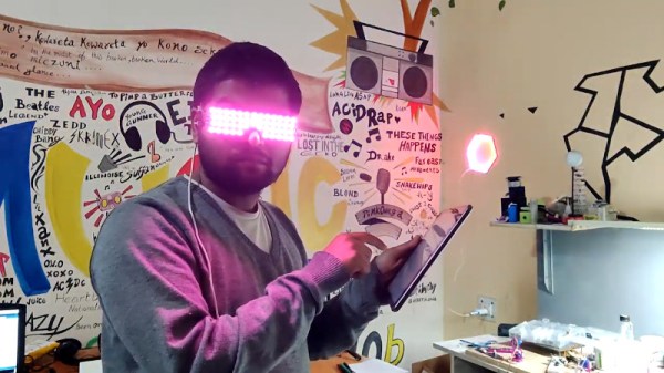
Pinephone Gets Thermal Imaging Backpack

When you buy a mass-market mobile phone, you’re making the decision to trust a long list of companies with your private data. While it’s difficult for any one consumer to fully audit even a single piece of consumer technology, there have been efforts to solve this problem to a degree. The Pinephone is one such example, with a focus on openness and allowing users to have full control over the hardware. [Martijn Braam] is a proud owner of such a device, and took advantage of this attitude to add a thermal imager to the handset.

The build is not a difficult one, thanks to the expansion-friendly nature of the Pinephone hardware. The rear of the phone sports six pogo pins carrying an I2C bus as well as power. [Martin] started by modifying the back cover of the phone with contacts to interface with the pogo pins. With this done, the MLX90640 thermal imager was attached to the case with double-sided tape and wired up to the interface.

While the 32×24 output from the sensor isn’t going to help you build cutting edge heat-seeking missiles, it’s an affordable sensor with good performance for low-end thermal imaging tasks. We’ve featured teardowns of thermal imaging hardware before, too.

Swimming Pool Lap Counter Relies On Ultrasound

Swimming is a great way to exercise, both for the cardiovascular benefits and the improved muscle tone. However, while he’s a fan, [Peter Quinn] sometimes finds it hard to keep track of how far he’s gone when he gets in the zone. Obviously, the solution is an electronic lap counter, which [Peter] promptly set about creating.

The build is based around an ultrasonic distance sensor, which is triggered when it detects a swimmer approaching the end of the lane. It’s run by an Arduino Nano, which is also set up to announce the accumulated distance with a speech synth library. [Peter] notes there have been some stumbling blocks thus far, necessitating modifications along the way. Water ingress into the ultrasonic sensor has required the installation of a protective shroud, while battery operation has required a module to properly handle the lithium-polymer battery.

While we might hesitate to bring a takeaway container full of wires, circuit boards and an LED display to a public pool for fear of being deemed a bomber, the basic bones of the project are a great way to approach the problem. There’s plenty of scope to implement laptiming too, as we’ve seen in other sporting builds!

Reverse Engineering The Charge Pump Of An 8086 Microprocessor

You’d think that the 8086 microprocessor, a 40-year-old chip with a mere 29,000 transistors on board that kicked off the 16-bit PC revolution, would have no more tales left to tell. But as [Ken Shirriff] discovered, reverse engineering the chip from die photos reveals some hidden depths.

The focus of [Ken]’s exploration of the venerable chip is the charge pump, a circuit that he explains was used to provide a bias voltage across the substrate of the chip. Early chips generally took this -5 volt bias voltage from a pin, which meant designers had to provide a bipolar power supply. To reduce the engineering effort needed to incorporate the 8086 into designs, Intel opted for an on-board charge pump to generate the bias voltage. The circuit consists of a ring oscillator made from a trio of inverters, a pair of transistors, and some diodes to act as check valves. By alternately charging a capacitor and switching its polarity relative to the substrate, the needed -5 volt bias is created.

Given the circuit required, it was pretty easy for [Ken] to locate it on the die. The charge pump takes up a relatively huge amount of die space, which speaks to the engineering decisions Intel made when deciding to include it. [Ken] drills down to a very low level on the circuit, with fascinating details on how the MOSFETs were constructed, and why eight transistors were used instead of two diodes. As usual, his die photos are top quality, as are his explanations of what’s going on down inside the silicon.

If you’re somehow just stumbling upon [Ken]’s body of work, you’re in for a real treat. To get you started, you’ll want to check out how he found pi baked into the silicon of the 8087 coprocessor, or perhaps his die-level exploration of different Game Boy audio chips.

Rotary Dialer Becomes Numeric Keypad

Many laptops eschew the numeric keypad to free up space, and some desktop keyboards have taken on the trend, too. If you want a specialised numeric entry device and have absolutely no interest in speed or ease of use, [jp3141] has just the build for you.

The idea is to use the rotary dial from an old telephone to enter numbers into a computer. It’s slow and cumbersome, but it’s also pretty entertaining. The build uses an old AT&T Trimline dialer, though we’re sure most rotary phones would work. The pulses produced by the dialer are counted by a Teensy microcontroller, which emulates a USB HID keyboard device and enters the relevant keystroke into the computer. There’s also a USB serial interface for debugging, and an LED which flashes along with the pulses from the dialer circuit.

While it’s not the most efficient data entry method, it’s a semi-useful way to repurpose an old phone, and an amusing piece to take along to your next LAN party. We’ve featured a few… alternative… keyboards before, too. If you’ve cooked up a truly convoluted input device for your computer, be sure to let us know.

Enjoying Some Exothermic Welding, With Thermite!

There probably aren’t many people out there who aren’t aware of what thermite is and how it demonstrates the power of runaway exothermic reactions. Practical applications that don’t involve destroying something are maybe less known. This is where the use of thermite for creating welds is rather interesting, as shown in this video by [Finn] that is also embedded after the break.

In the video, one can see how [Finn] uses thermite charges to weld massive copper conductors together in a matter of seconds inside a graphite mold. Straight joints, T-joints, and others are a matter of putting the conductors into the mold, pushing a button and watching the fireworks. After a bit of cleaning the slag off, a solid, durable weld is left behind.

The official name for this process is ‘exothermic welding‘, and it has been in use since the 19th century. Back then it was used primarily for rail welding. These days it sees a lot of use in high-voltage wiring and other applications, as in the linked video. The obvious advantage of exothermic welding is that the resulting joint is strong and durable, on account of the two surfaces having been permanently joined.

Continue reading “Enjoying Some Exothermic Welding, With Thermite!”

Breakaway Keyboard PCB Makes Customization A Snap

Once upon a time, keyboards were something that you took with you from computer to computer, because most of them were built quite nicely. After a few dark decades of membrane keyboards being the norm, the rise of the mechanical keyboard community has shined a light on what is possible with open source designs. Anyone can join in, because quality clackers now exist on every level, whether you want to design the perfect split ortho with OLEDs, rotary encoders, and rear view mirrors, or just want to fork over some money and get to punching switches.

Break me off a piece of that candy bar keeb.

Building your own keyboard doesn’t have to be daunting. It can be as easy or as involved as you want. There’s still a fair amount of soldering simply because it’s a keyboard. But there are plenty of options if you don’t want to do a whole lot beyond soldering switches (or hot swap sockets!) and putting a case together.

Take for instance the JNAO (Just Need An Ortho) build that [Jared] just finished. It starts with a PCB and on-board controller, and the idea is to customize it from there. You’re left to 3D print, laser cut, or otherwise carve your own case and a plate to stabilize the key switches, and then get down to business deciding on switches and keycaps.

The interesting thing about the JNAO is the breakaway row of keys on the bottom. The standard grid is 12×5, but if you don’t need the dedicated number row along the top like [Jared], you’re not stuck with it. And you’re not stuck with the default layout, either. Flashing to a standard Planck layout didn’t go as easily as [Jared] might have liked, but we think he was wise to get the firmware squared away before ever turning on the soldering iron.

Don’t know what to do with such a small keyboard? They’re pretty much perfect for cyberdeck builds.

Trick From 1903 Makes An Old Monochrome TV Spit Some Colours

Its safe to say that colour television is taken for granted nowadays. Consumed by the modern marketing jargon of colour dynamic range, colour space accuracy and depth, it is easy to overlook the humble beginnings of image reproduction when simply reconstructing an image with the slightest hint of colour required some serious ingenuity and earned you a well deserved pat on the back!

[anfractuosus] revisited an old gem of a technique, first patented in 1903 and used it to successful make an old monochrome TV produce a colour image. The idea in essence, is actually similar to what cheap image sensors and LCDs still use today. Rather than relying on true RGB colour generation by individually integrating colour sources as AMOLED does, we take an easier route: Produce a simpler monochrome image where each colour pixel is physically represented by four monochrome sub-pixels, one for each colour component. Now light up each of the sub-pixels according to the colour information of your image and rely on an external colour filter array to combine and spit out the correct colours.

He first used some image processing to convert a standard colour video into the aforementioned monochrome sub-pixel representation. Next, a Bayer colour filter array was printed on some acetate sheets using an inkjet printer (the original inventors used potato starch!), which when overlaid on top of the monochrome monitor, magically result in colour output.

There are some problems associated with this technique, mainly to do with the difficulty in measuring the size of the TV pixels and then producing and perfectly aligning a filter sheet for it. You should check out how [anfractuosus] went about solving those issues.

So now you know a bit more about colour image generation, but how about colour TV transmission? Check out an earlier piece to learn more.

Continue reading “Trick From 1903 Makes An Old Monochrome TV Spit Some Colours”