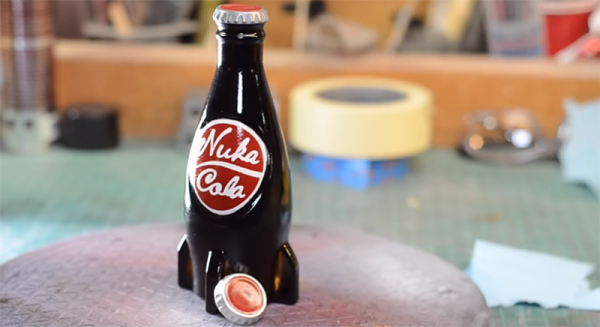
There’s less than a month until the next Star Wars is released, and consequently a few weeks until amateur propmakers and cosplayers go insane fabricating their own lightsabers with lightsaber cross guards and rolling robots. Until then, Fallout is pretty cool and [Bill] is here to give us an introduction to prop making with one of the defining objects of this post-apocalyptic universe. He created a real life copy of a Nuka Cola bottle and created a great introduction to resin casting in the process.
As with all proper part making endeavours, this project began with getting reasonably accurate models of the object to be copied. In Fallout, we’re lucky enough to have a way to look at a specific object while zooming and spinning around it, giving [Bill] the basic shape. The size was rather easy as well: all bottlecaps are the same size, so [Bill] just scaled the model to that.
With the model created and the part printed out, assembled, and finished, it was time to create the mold. [Bill] used a two-part silicone mold for the basic shape. The actual casting was done by rolling around a little resin on the inside of the mold. There’s no need for a solid, bottle-shaped block of resin; bottles are hollow anyway.
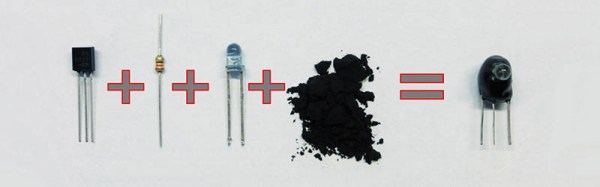
There are a few neat tricks [Bill] has up his sleeve, including coating the inside of the mold with aluminum powder and using a vinyl cutter to get the labels and logos exactly right. The finished product turns out great, perfect for leaving in the Wasteland for 200 years until the Sole Survivor stumbles upon it.
Video below.
Continue reading “An Introduction To Casting With Nuka Cola” →

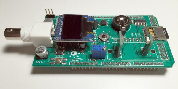
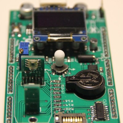 Taking the form of an Arduino mega-shield that supports a pH meter, a spectrophotometer, and a PID-controlled hot plate, [M. Bindhammer]’s design has a nice cross-section of the instruments needed to start biohacking in your basement. Since the shield piggybacks on an Arduino, all the data can be logged, and decisions can be made based on the data as it is collected. One example is changing the temperature of the hot plate when a certain pH is reached. Not having to babysit your experiments could be a huge boon to the basement biohacker.