Golden Commodore C64 Brings The Bling To 8-Bit Computing

Sometimes, a hack is just a hack. And sometimes, a hack is nothing but a gold-plated Commodore C64.

Alright, it’s not gold-plated, it’s gilded. For the uninitiated, gilding is the process of gluing gold powder or gold leaf to an object. Gold is amazingly ductile – a tiny nugget 5mm in diameter can be hammered into a sheet of gold leaf that can cover about a half a square meter. It’s extremely thin and delicate and has to be handled very gingerly, and the gilder’s craft is therefore very meticulous. For more on gilding, see this post on signmaking with gold leaf.

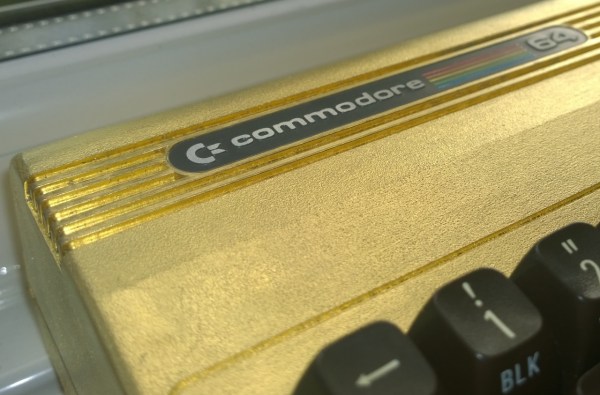
[thefuturewas8bit], who runs a vintage Commodore web store, did a great job gilding a C64 case, just because. The attention to detail is fantastic – notice that even the edges of the keyboard cutouts are gilded and burnished. A nice finishing touch is swapping out the stock red power LED for a yellow one – red simply clashes too much. Lest you think there’s nothing to learn from a purely aesthetic hack, [thefuturewas8bit] shares a great tip for removing the metal badges from a plastic case – spray them with freeze-spray from the back to pop off the glue. No need to dig at them with a screwdriver and gouge or bend them. Nice trick.

Any hack can earn extra points for style, and we think that gold works well on the C64.  But if gold is a little too overstated for you, you can always try to score a colorful new injection-molded case for your vintage Commodore.

Visualizing The Fourier Transform

If you do any electronics work–especially digital signal processing–you probably know that any signal can be decomposed into a bunch of sine waves. Conversely, you can generate any signal by adding up a bunch of sine waves. For example, consider a square wave. A square wave of frequency F can be made with a sine wave of frequency F along with all of its odd harmonics (that is, 3F, 5F, 7F, etc.). Of course, to get a perfect square wave, you need an infinite number of odd harmonics, but in practice only a few will do the job.

Like a lot of abstract concepts, it is easy to understand the basic premise and you could look up any of the mathematical algorithms that can take a signal and perform a Fourier transform on it. But can you visualize why the transform works the way it does? If you can’t (or even if you can), you should check out [Mehmet’s] MATLAB visualization of harmonic circles. If you don’t have MATLAB yourself, you can always check out the video (see below).

Continue reading “Visualizing The Fourier Transform”

Over-the-top Hackerspace Donation Box Brings Out The Brony In You

“You’ll never believe how this happened, doc.” [Source: CRASH Space]
If you’re going to pass the hat for donations to your hackerspace, you might as well add to the value proposition and give potential donors a little something for their generosity. And what better way to cash in than to channel the inner Brony in your donors with a My Little Pony themed dollar-bill vortex box?

Sick of the boring cheezy-poof jug her hackerspace was using as a donation jar, not-a-Brony [Michelle] was inspired by the CRASH Space mascot Sparkles, pictured left, to build a new box that will maximize donations by providing donors with a multimedia extravaganza. The Plexiglas box, resplendent with laser-cut acrylic hearts and spangled with My Little Pony stickers, is fitted with a sensor so that donations trigger an MP3 of the MLP theme song. A scrolling LED marquee flashes a gracious message of thanks, and to complete the experience, a pair of fans creates a tornado of the fat stacks of cash in the bin.

Putting a little [Twilight Sparkle] into your donation box makes good financial sense, as does providing incentive to deposit bills rather than coins. This project reminds us of our recent post about a custom claw machine which could be leveraged as a value-added donation box – just add a coin slot. And rainbows.

Continue reading “Over-the-top Hackerspace Donation Box Brings Out The Brony In You”

Full Size Custom Claw Machine Built With Parts On Hand

You know how it goes – sometimes you look at your social calendar and realize that you need to throw together a quick claw machine. Such was the dilemma that [Bob Johnson] found himself in during the run-up to the Nashville Mini Maker Faire, and he came up with a nice design that looks like fun for the faire-goers.

Seeking to both entertain and enlighten the crowd while providing them with sweet, sweet candy, [Bob] was able to quickly knock together a claw machine using mainly parts he had on hand in the shop. The cabinet is nicely designed for game play and to show off the gantry mechanism, which uses aluminum angle profiles and skate bearings as custom linear slides. Plenty of 3D printed parts found their way into the build, from pillow blocks and brackets for the stepper motors to the servo-driven claw mechanism. A nice control panel and some color-coded LED lighting adds some zip to the look, and a Teensy LC runs the whole thing.

Like [Bob]’s game, claw machines that make it to Hackaday seem to be special occasion builds, like this claw machine built for a kid’s birthday party. Occasion or not, though, we think that fun builds like these bring the party with them.

Continue reading “Full Size Custom Claw Machine Built With Parts On Hand”

Smart Phone Camera Turns Laser Cutter Into Hi-Res Scanner

Getting decent macro photos always seems to be a chore. Some important detail always seems to be just outside of the depth of field, or you have to be zoomed in so close that you get great detail in one spot but miss the big picture. [Nate B] had such a problem while trying to document some PC boards, and he came up with a nifty hack that uses a laser cutter and a smart phone camera to do the job.

Pv150a-front
Click for detail.

Having first tried scanning the boards with a flat-bed scanner but finding the depth of field unsatisfactory, [Nate B] then went on to his Samsung phone’s camera. Set to panorama mode, he manually scanned across the boards and let the camera stitch the images together. The results were better, but the wobblies got the better of him and the images showed it. He then decided to use a laser cutter — with the laser disabled, of course — as an impromptu X-Y stage to raster his camera above the boards. In a slightly cringe-worthy move, he gingerly clamped the phone to the cutter gantry, started the panorama, and let the cutter move over the board. This results in a rock-solid pictures of his boards with a lot of detail – perfect for his documentation. As a bonus, the honeycomb laser cutter bed makes for an interesting background texture.

Obviously anything could be used to raster a camera and achieve similar results, but full points here for maximizing available resources and not over-complicating a simple job. Yet another reason you can use to justify that laser-cutter purchase.

Continue reading “Smart Phone Camera Turns Laser Cutter Into Hi-Res Scanner”

LED Matrix Failure And Vindication

If necessity is the mother of invention, what’s failure the mother of? Improvement? Anyway, [prpplague]’s second version of his roll-up 70×30 RGB LED display looks a lot better and more reliable than the first, and that’s precisely due to “failing”.

Sometimes you design the hardware around the software, and sometimes vice-versa. It’s all about the balance of pain. [prpplague] initially wired the strips together in a consistently left-to-right raster arrangement to make the coding easier, but this means long wires on the backside of the fabric returning from the right side back to the start again at the left. These long wires snagged on stuff, and pulled the solder connections apart.

600px-Dotstar-adapter-solder3The fix? Alternate rows of left-to-right with right-to-left to minimize wiring and make nice, robust connectors for the ends, and a much more elegant implementation at the expense of more complicated software to drive the device. (Alternating rows have to be flipped horizontally, so this means custom driver routines.)

The second gremlin was that the interfacing board that [prpplague] was using didn’t have enough current sourcing capability on the SPI lines, and he discovered that he couldn’t communicate reliably with the strings if the first pixel was more than 24″ of wire away from the board. Once the signal got to the first pixel, though, everything was fine. [prpplague] figured out that the RGB LEDs themselves had more drive capability than the SPI source.

The solution? Add a single pixel at the front of the chain to buffer the SPI lines and serve as a bonus status indicator. Cute.

We’d hardly call these “fails”, but rather “learning experiences”. Anyway, here’s two design “mistakes” that we won’t make when making a roll-up flexible pixel display. Thanks [prpplague].

Better Batteries For Electronic Gadgets

We’re not using 9 Volt batteries to power our projects anymore; the world of hobby electronics has moved on to cheap LiPo batteries for most of our mobile power storage. LiPos aren’t the best solution, evidenced by hundreds of YouTube videos of exploding batteries, and more than a few puffy cells in our junk drawer. The solution? LiFePO4, or lithium iron phosphate cells. They’re a safer chemistry, they have low self discharge, and have more recharge than other chemistry of lithium cells.

LiFePO4 cells aren’t easy to deal with if you’re working with breadboard electronics, though. Most of that is because there aren’t many breakout boards for these cells. [Patrick] is working on changing that with his LiFePO4werd USB charger.

The concept is simple: use an off-the-shelf part for LiFePO4 batteries – in this case an MCP73123 – and make a board that charges the batteries with a USB port. It’s exactly the same idea as the many USB LiPo chargers out there, only this one uses a better battery chemistry.

[Patrick] is using a 550mAh battery for this project, but there’s no reason why it couldn’t be upgraded to a 18650-sized cell with more than 2000mAh stuffed inside. Add a boost converter to the circuit, and he’ll have the perfect power source for every portable electronics project imaginable.