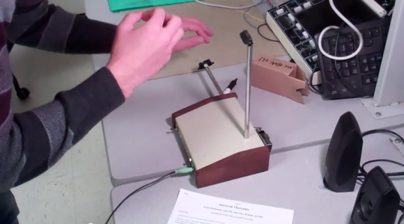
Here’s a musical entry for the Fubarino Contest that turned out to be rather delightful. First, [Mats] shows off his musical knowledge by using the notes H, A, and D to play the chord that unlocks the Easter eggs. What’s that you say? There’s no H on your keyboard? You’re wrong. In the German music tradition B natural is known as H. This is what allowed Bach to write a tune that spells his name.
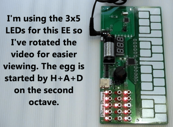
[Mats] is hacking on his PlingPlong synthesizer. The first Easter egg—which you can see in the clip after the break—launches with the H-A-D chord in the lower octave, spelling out our URL on the 7-segment displays. But we prefer the second egg, launched with the chord in the upper octave, which is shown above. It uses the 3×5 LED grid to scroll out the address; in this still image an H is displayed.
This is an entry in the Fubarino Contest for a chance at one of the 20 Fubarino SD boards which Microchip has put up as prizes!