Electro-permanent magnets (EPMs) are pretty nifty concepts, and if you aren’t familiar with them, they are permanent magnets with the ability to be electrically switched on or off. Unlike an electromagnet — which maintains a magnetic field only while power is applied — an EPM can remain “on” even when power is removed. Want to see one work? There’s a video embedded below that shows one off, but if you’d like to know how they work, we have you covered.
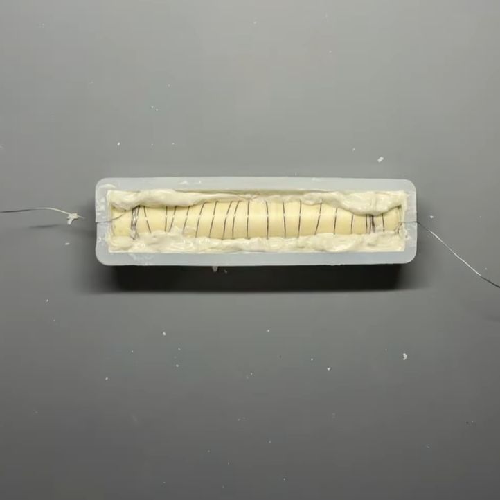
Inside are two types of magnet, one of which is permanent and the other being a semi-hard magnet paired with an electromagnetic coil. A semi-hard magnet’s flux can be changed by exposing it to a strong enough magnetic field, and that’s the key to making it work.
When both magnets work together, the EPM is “on” and acts like a permanent magnet. To turn the EPM off, the polarity of the semi-hard magnet is flipped with a short and powerful electromagnetic pulse, after which the two magnets oppose one another and more or less cancel each other out. So rather than generating a magnetic field, an EPM more accurately reconfigures it.
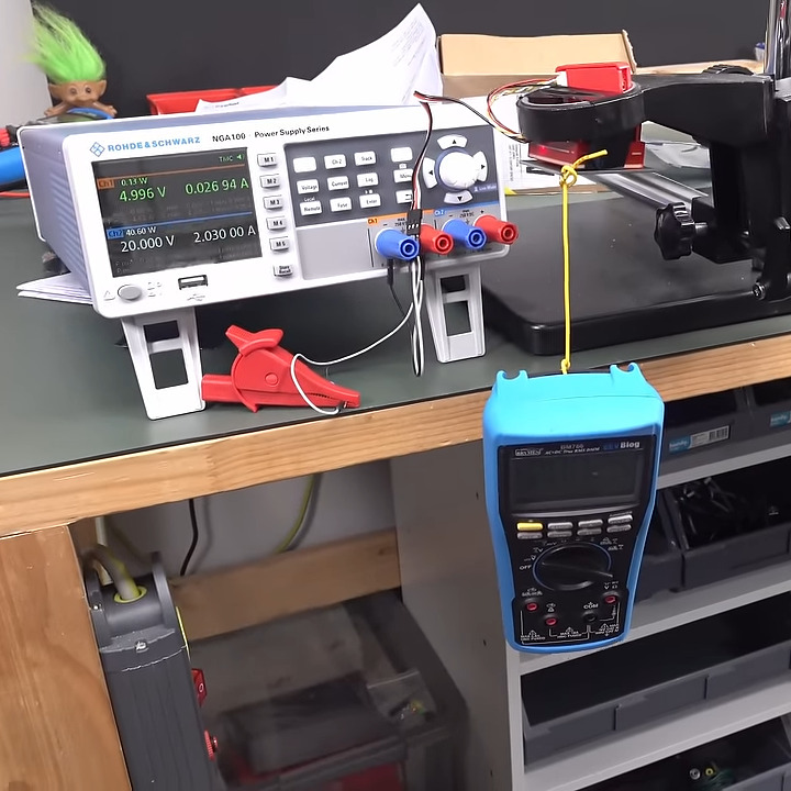
As intriguing as EPMs are, we haven’t really seen one properly in action until it was brought to our attention that [Dave Jones] of EEVblog tried one out last year. He received a Zubax FluxGrip EPM, which is intended for drone and robotic applications and can hold up to 25 kg. Watch [Dave] fire it up in the video (link is cued up to the 7:30 mark), it’s pretty interesting to see one of these actually work.
EPMs are not prohibitively expensive but they are not exactly cheap, either. But if a switchable magnet sounds up your alley and you can’t afford an EPM, consider an alternative “switchable” magnet design that works by momentarily canceling out a permanent magnet with a paired electromagnet. Unlike an EPM, it’s not a permanent switch but it would be enough to drop a payload.
Continue reading “Watch An Electro-Permanent Magnet In Action”