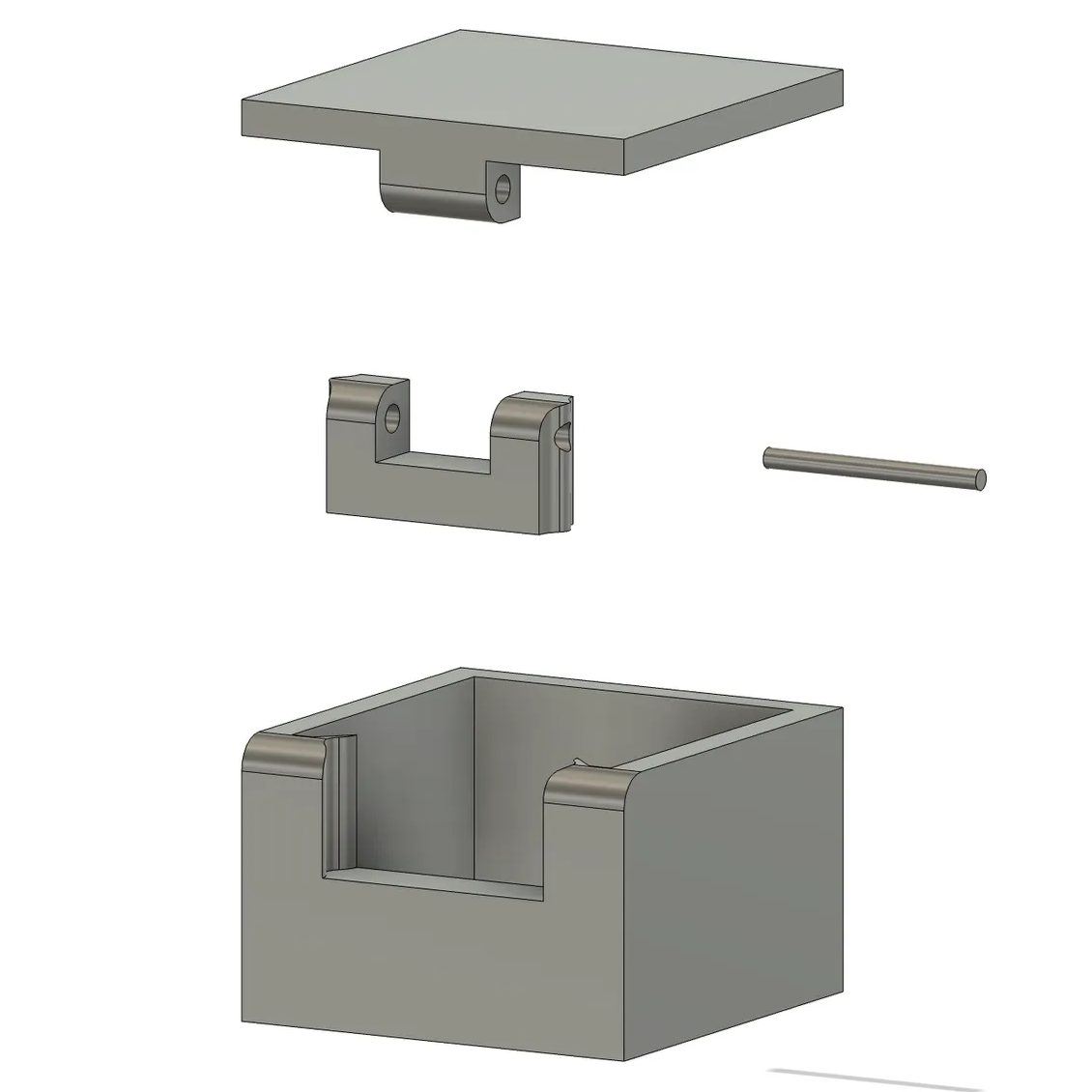
This design (shown in this simple box as an example) makes a very close-fitting hinge point.
This design prints half the hinge as a separate piece — the u-shaped one in the picture to the side — that must be glued into the target object after printing. It’s a bit of extra work, but doing it this way has a couple advantages.
One is that printing some of the hinge elements separately means one no longer needs to choose between a print orientation that best suits the object, and a print orientation that works best for the hinge. Also, the length of 1.75 mm filament used as a hinge pin is held captive after assembly so there’s no need to glue the hinge pin itself.
[Alex] helpfully provides the parts in STEP format, which makes CAD tweaks and adjustments easy. While incorporating the design should be doable even if one is just using .stl or .3mf files because boolean subtraction and merging is all that’s needed, having the model in STEP format is so much better.
Should you need some pointers on incorporating either into FreeCAD, we have you covered.
First introduced in 1979 by Signetics, the NE5532 was a pretty spiffy dual op-amp for the time with low noise and low distortion. Over the years it has become a standard part that showed up in countless audio products, and has become a so-called jellybean generic component with Texas Instruments (TI) being one of countless manufacturers.
It being such a standard, multi-sourced part makes it thus even more puzzling that TI has now decided to completely overhaul this IC in a way that makes it incompatible with even the original Signetics NE5532. These changes are covered in detail by [Dave] of EEVblog as his mind is pretty much blown at such an incomprehensible change.
The changes entail an entirely different manufacturing process and a big change in specifications, while making no change to the part number. In revision K of the TI datasheet these changes are first seen, with some specifications changed for the better, like a higher unity gain bandwidth by 2 MHz, but a much slower slew rate.
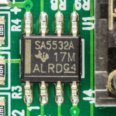
Texas Instruments SA5532A variant of the 5532 op-amp. (Credit: Raimond Spekking, Wikimedia)
Although the 5532 op-amps are multi-sourced, there are good reasons to just stick with manufacturers like TI, as that means receiving a product change notification (PCN) when anything changes. In the PCN related to this op-amp a change to process node is noted, along with other changes, but no reasoning.
Among the other big changes are a reduction in the supply voltage from 22 V to 18 V, and a halving of the ESD protection from 2 kV to 1 kV. Although it might be slightly more efficient on the new process node this way, it clearly comes with a lot of trade-offs that make it an overall worse op-amp, while also being incompatible with the same op-amp from other manufacturers.
In the video [Dave] goes through the datasheets of this jellybean part of other manufacturers, showing that they still have the original 1980s specifications. Only one exception here was the NE5532DR from Shenzhen HuaXuanYang Electronics, whose supply rail voltage is also 18 V for some reason, along with a similar internal transistor configuration that reduces the ESD resistance.
In addition to the NE5532 op-amp, it seems that TI also took an axe to the OPA134 op-amp, by removing its offset trim feature and listing the pins as ‘NC’, with a warning to not connect these pins and also worsening other specifications. This makes these similar jellybean parts incompatible, with no change to the part number. Worse is that it continues with the LMH6518, whose changes [Dave] argues might even kill oscilloscopes as they are commonly found in those.
Meanwhile the LM317M also got an overhaul, but here TI opted to give it a new part name, calling it the LM317MQ with at first glance no major degradations in the specifications, but instead some actual improvements. This makes it even more puzzling why TI didn’t give the other ICs a new part number to differentiate them from the jellybean part.
Until there’s some clarification from the side of TI, it might be a good idea to source these parts from a manufacturer that is not TI, especially when replacing these ICs in older devices.
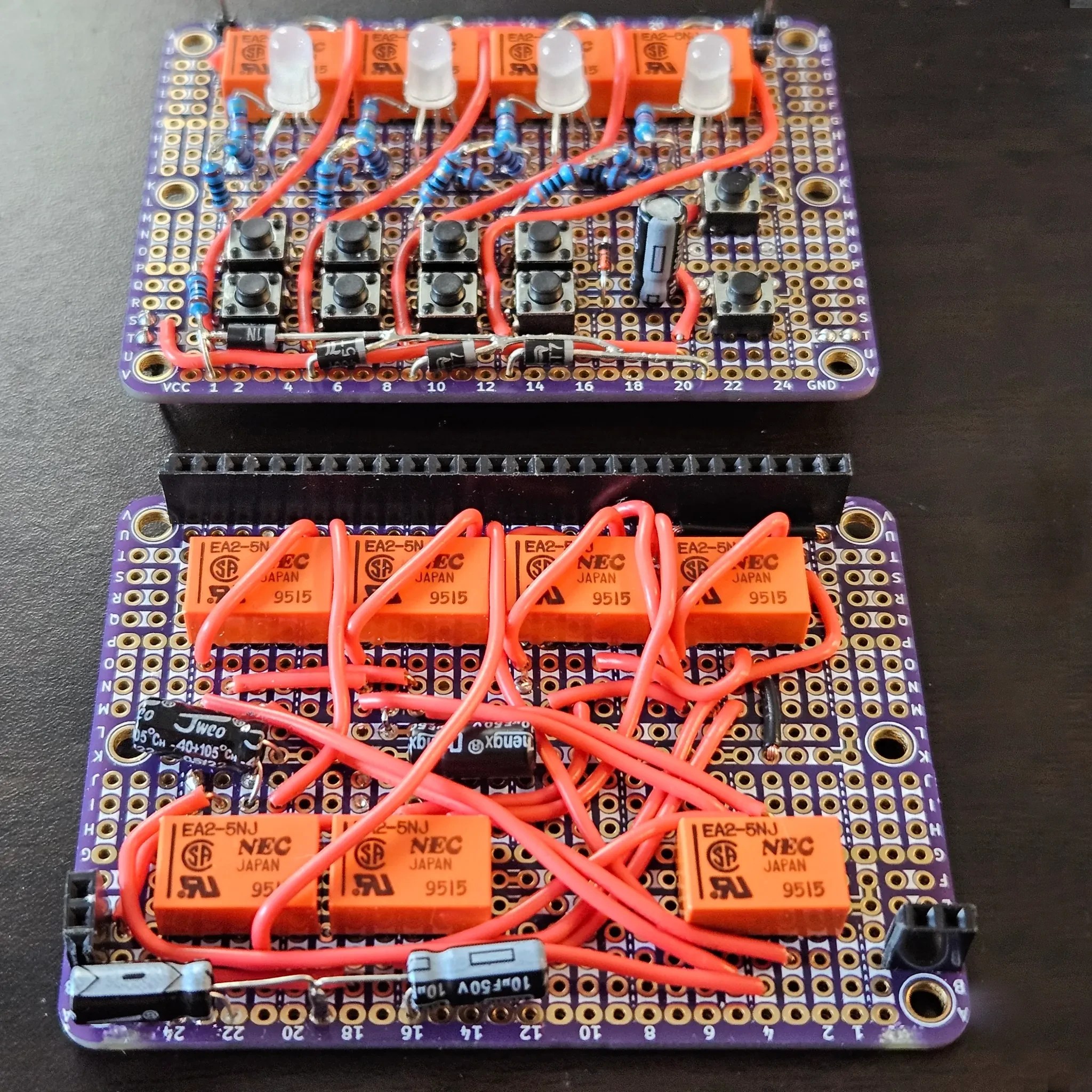
The register with LEDs and buttons is on the top board, the incrementer on the bottom board.
[Agatha Mallett] made the counter after finding herself in possession of a quantity of relays burdened by terrible documentation (the datasheet shockingly lacks a pinout, and doesn’t even mention the coil being unidirectional). But since the relays are also small and of decent quality, they were a good candidate for a small relay logic-based project.
The key to the build is implementing D-type flip-flops using relays. This is done by holding the coil voltage of each relay between its set and release voltage levels. A small voltage bump will energize the coil, closing the relay and leaving it closed. Conversely, a small negative spike releases the coil, leaving it open. This forms the basis of the counter, and [Agatha] has a separate write-up all about the details of using relays in this way.
Implementing this was rather less straightforward than it may sound because it relies on balancing the coils of many relays on a figurative knife-edge of voltage, but not every component is perfectly identical. A tweaked resistor or capacitor here and there was needed before things settled into reliability.
The end product has indicator LEDs, buttons to increment or clear the current count, and it even has buttons to set or clear individual bits. This is a project that begs to be interacted with, and there’s a short video on the project page so you can watch it go through its paces.
A potentiometer is a simple electrical device that allows resistance to be varied at will. Most everyone in the electronics field is intimately familiar with how they work on a fundamental level. Of course, we all had to be taught once, though, and a great way to do that would be with a teaching tool like the one [DiscoLapy] built.
What you’re looking at here is a very simple potentiometer that bares its function for all to see. It consists of a 3D printed base and knob, which form the mechanical part of the device. A paper track is then laid on top to act as the main resistive element, once properly covered with graphite from a regular old pencil. From there, it’s as simple as adding the necessary contacts and wiper to the device, and you’ve got a potentiometer sitting in front of you.
What’s great about this build is that it’s very intuitive. Just by looking at it or putting it together, you get a straightforward understanding of everything that’s going on. By drawing the resistive trace, and by turning the knob, particularly if hooked up to an LED or something like in the demonstration, it’s easy to see how the potentiometer varies its resistance and affects a circuit.
These days wireless microcontrollers featuring built-in WiFi and Bluetooth are all the rage, with Espressif’s range of ESP32 MCUs being the default option for commercial and hobbyist projects alike. This makes Qualcomm’s recently released QCC74x MCU rather interesting, as specification-wise it would seem to be placed firmly in ESP32 territory.
On the radio side you get 1×1 WiFi 6, Bluetooth 5.4, and IEEE 802.15.4 (e.g. Thread and Zigbee), coupled with a single-core 352 MHz RISC-V CPU with FPU and DSP features and 484 kB of SRAM. The SDK for this MCU is hosted on Codelinaro, featuring the typical FreeRTOS-based stack, though confusingly Bluetooth and Zigbee support are currently marked as ‘not supported’. This might still be in progress.
Where the competition with Espressif feels clear is in the pricing, with the highest-performance evaluation board (QCC748M EVK, pictured above) listed for $13 (before taxes/tariffs). This gets you 8 MB of PSRAM built-in with unspecified link speed, but likely the same QSPI as used for the NOR Flash. USB support is available on this higher-end tier, while absent on the QCC743. Development documentation is also available, and looks fairly complete based on first glance.
Overall the QCC74x looks to be an upgrade to the older and significantly less powerful QCC730 MCU. Depending on software support and final pricing it could make for an interesting competitor to some of Espressif’s modules like its ESP32-C series or ESP32-S2, though the upcoming ESP32-S31 would seem to have it matched or beat on all metrics.
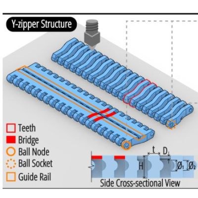
Along with Velcro, zippers have become an integral part of every day life, being a quick and easy way to usually temporarily join fabric together. Which isn’t to say that you cannot do more with the basic zipper concept, including using them to turn floppy 2D shapes into rigid 3D ones, such as with the Y-zipper concept proposed and demonstrated by [Jiaji Li] et al.
Although not a fully new idea, the Y-zipper is compared with a range of similar mechanisms that do not feature the same abilities, including the standard zipper ease of zipping up, the possibility of having curved geometry and automatic actuation.
Plus there is that the Y-zipper is designed from the start to be 3Dprinted, while still following the same basic pattern of interlocking teeth that the slider mechanism alternately pushes together or pulls apart.
By modifying the basic straight design of the flat strips, the resulting zipped-up form can take on a distinct bend, as well as turn into a coil or a screw. With a demonstrated joint design it is then possible to join multiple Y-zipper rods together, which could make for an interesting alternative to traditional pop-up tent supports, for example.
Also demonstrated is the use of TPU to create compliant bridges, as well as the direct integration of fabric, to show the versatility of the technology. With the used materials (PLA, TPU) the researchers estimate a maximum viable length of about 3 meters before the printed structures begin to disintegrate.
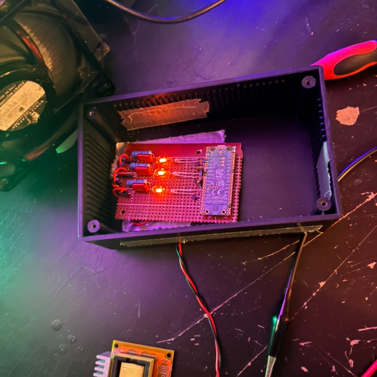
The quest for true randomness has roots in cryptography and is a rabbit hole that gets surprisingly deep with alarmingly rapidity. Still, the generation of random-enough numbers is a popular hacker project. Part of the appeal is the way these devices strive to incorporate physical phenomena, and in [Joshua Coleman]’s case, his Neon Entropy (Pseudo) Random Number Generator uses a trio of vintage neon lamps.
Neon lamps discharge at rates that vary unpredictably. They’re also pretty to look at.
[Joshua] chose neon lamps in part because the discharge rate of an energized lamp is a variable, physical process that makes a good source of entropy. They also have an attractive visual appeal that fits the concept [Joshua] had in mind. Unlike random number generators that kick off by measuring radiation or some other imperceptible thing, it’s possible — at least in a sense — to see this one working.
The small variations in the three neon lamps are measured optically by three TEPT4400 ambient light sensors (isolated from the neon lamps themselves) and turned into analog signals. A Raspberry Pi Pico W reads these signals, then uses them in a process that culminates in SHA-256 64-bit values that can be used as random seeds.
There’s also a web dashboard that shows everything live, furthering the “watch it work” concept [Joshua] is aiming for. The video below shows the project in action if you want to see how the sausage gets made.
Earlier we mentioned how random number generators are popular projects among hackers, and here are a few selected ones. Don’t miss the stylish glow and slick enclosure of this Nixie tube RNG, or the lava lamp RNG which is in fact not a gimmick. And while it is commonly understood that meaningful randomness must come from outside a digital chip, uninitialized internal volatile RAM — if accessed correctly — can be a remarkably good source of entropy.