Making A Nichrome Wirewound Power Resistor

Although not really a cost-effective or a required skill unless you have some very specific needs not met by off-the-shelf power resistor options, making your own own wirewound power resistor is definitely educational, as well as a fascinating look at a common part that few people spare a thought on. Cue [TheElectronBench]’s video tutorial on how to make one of these components from scratch.

The resistance value is determined by the length of nichrome wire, which is an alloy of nickel and chromium (NiCr) with a resistivity of around 1.12 µΩ/m. It’s also extremely durable when heated, as it forms a protective outer layer of chromium oxide. This makes it suitable for very high power levels, but also requires the rest of the power resistor assembly to be able to take a similar punishment.

For the inner tube of this DIY power resistor a tube of alumina ceramic was used, around which the nichrome wire is wound. This resistor targets 15 Ohm at a maximum load of 50 Watt, this means a current of about 1.83 A is expected at 27.4 V. The used nichrome wire has a measured resistance of 10.4 Ohm, ergo 1.44 meter has to be cut and wound.

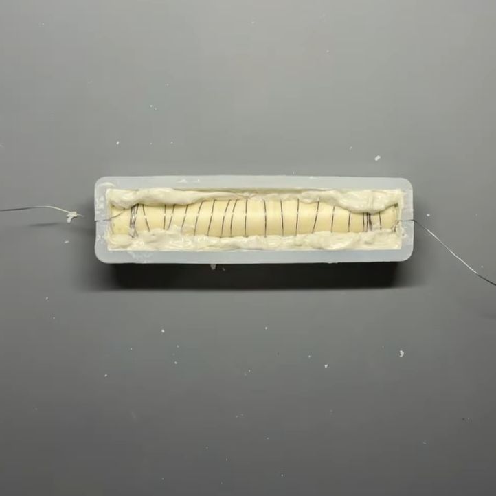
This entire assembly is then embedded in refractory cement (fireproof cement), as this will keep the wire in place, while also able to take the intense temperature cycling during operation. As a bonus this will prevent toasting the surrounding environment too much, never mind lighting things on fire as the nichrome wire heats up.

As explained in the video, this is hardly the only way to create such a power resistor, with multiple types of alternative alloys available, different cores to wind around and various options to embed the assembly. The demonstrated method is however one that should give solid results and be well within the capabilities and budget of a hobbyist.

An important point with nichrome is that you cannot really solder to it, so you’ll need something along the lines of a mechanical (crimping) connection. There are also different winding methods that can affect the inductance of the resistor, since this type of resistor is by its design also a coil. This is however not covered in the video as for most applications it’s not an issue.

Overall, this video tutorial would seem to be a solid introduction to nichrome power resistors, including coverage of many issues you may encounter along the way. Feel free to sound off in the comment section with your own experiences with power resistors, especially if you made them as well.

ESP32: When Is A P4 A P4, But Not The P4 You Thought It Was

We’re used to electronic parts of the same type staying predictably the same, sometimes over many years. An early Z80 from the mid 1970s can be exchanged with one from the end of production a few years ago, for example. This week, we’ve had DMs from several readers who’ve found that this is not always the case, and the culprit is surprising. Espressif has released a new revision of their P4 application processor, and though it’s ostensibly the same, there are a couple of changes that have been catching people out.

The changes lie in both hardware and software, in that there’s a pin that’s changed from NC to a power rail, a few extra passives are needed, and firmware must be compiled separately for either revision. The problem is that they are being sold as the same device and appear in some places under the same SKU! This is leading to uncertainty as to which P4 revision is in stock at wholesalers. We’ve been told about boards designed for the old revision being assembled with the new one, a situation difficult to rework your way out of. Designers are also left uncertain as to which firmware build is needed for boards assembled in remote factories.

The ESP32-P4 is an impressive part for its price, and we’re sure that we’ll be seeing plenty of projects using this new revision over the coming years. We’re surprised that it doesn’t have a different enough part number and that the wholesalers have seemingly been caught napping by the change. We’re told that some of the well-known Chinese assembly houses are now carrying the two chips as separate SKUs, but that’s scant consolation for a designer with a pile of boards carrying the wrong part. If you’re working with the P4, watch out, make sure your board is designed for the latest revision, and ask your supplier to check which chips you’ll get.

If the P4 is new to you, we’ve already seen a few projects using it.

The Shockley 4-Layer Diode In 2026

The physicist William Shockley is perhaps today best known for three things: his role in the invention of the transistor, his calamitous management of Shockley Semiconductor which led to a mass defection of employees and precipitated the birth of the Silicon Valley we know, and his later descent into promoting eugenics. This was not the sum of his work though, and [David Prutchi] has been experimenting with a now-mostly-forgotten device that bears the Shockley name (PDF), after finding one used in an early heart pacemaker circuit.  His findings are both comprehensive and fascinating.

The Shockley diode, or 4-layer diode as it later became known, is as its name suggests a two terminal device with a 4-layer NPNP structure. It can be modeled as a pair of complementary transistors in parallel with a reverse biased diode, and the avalanche breakdown characteristics of that diode when a particular voltage is applied to it provide the impetus to turn on the two transistors. This makes it a voltage controlled switch, that activates when the voltage across it reaches that value.

The PDF linked above goes into the Shockley diode applications, and in them we find a range of relaxation oscillators, switches, and logic circuits. The oscillators in particular could be made with the barest minimum of components, important in a time when each semiconductor device could be very expensive. It may have faded into obscurity as it was superseded by more versatile 4-layer devices such as the PUJT or silicon-controlled switch and then integrated circuits, but he makes the point that its thyristor cousin is still very much with us.

This appears to be the first time we’ve featured a 4-layer diode, but we’ve certainly covered the genesis of the transistor in the past.

A Rotary Dial The 3D Printed Way

There’s a meme which may have a basis in truth, of a teenager left clueless when presented with a rotary telephone. The dial, in reality a mechanical pulse chain generator, was once ubiquitous enough that having one in your parts bin was anything but unusual. If you’re curious about their inner workings in 2026 though, you may be out of luck. Never fear though, because [Moeya 3D Designs] is here with a fully 3D printed version. It’s not as compact as the original, but it’s all there.

If you’re not put off by the anime-style Japanese voice over on the video below the break and you can enable subtitles for your language, you get the full explanation. There’s a ratchet and spring on the dial, which when released drives a gear train that ends in a cam that would operate a switch for the pulses. Another set of gears drives a very neatly designed centrifugal speed governor, and we see the effect immediately when it is removed. We’re not sure who will go for this project, but we surely like it.

There are two videos below the break, with the dial shown off in the first and the design process in the second. Meanwhile we’ve talked in the past about the networks behind the dials. Continue reading “A Rotary Dial The 3D Printed Way”

Arduino’s New AI-Centric Board Is The VENTUNO Q

There have been many questions about what direction Arduino would take after being bought by Qualcomm. Now it would seem that we’re getting a clearer picture. Perhaps unsurprisingly the answer appears to be ‘AI’, with the new Arduino VENTUNO Q SBC being advertised as ‘democratizing AI’ in the Qualcomm press release, although it also references robotics.

This new board is based around the Dragonwing IQ-8275 SoC along with an STM32H5F5 MCU, making it somewhat of a beefier brother of the previously covered Arduino Uno Q, which also offers an SoC/MCU hybrid solution. On the product page we can see the overall specifications for this new board, where the release date is specified as ‘soon’.

Its IQ-8275 SoC is part of Qualcomm’s IQ8 series, with eight 2.35 GHz ARM cores and an Adreno 623 GPU, paired with 16 GB of LPDDR5. The Cortex M33-based STM32H5F5 MCU comes with its own 4 MB of Flash and 1.5 MB of RAM, all on a board that’s significantly larger than the Uno Q and isn’t crippled by a single USB-C port as SoC I/O.

Although clearly more aimed at industrial and automation applications than the solution-in-search-of-a-problem Uno Q board, it remains to be seen whether this board will catch on with Arduino fans, or whether Qualcomm’s goal is more to break into whole new markets under the Arduino brand.

NaCl Casting Technique Really Earns Its Salt

Sodium Chloride has a melting point of 801 C (1,474 F), putting it comfortably between commonly-cast materials like aluminum and bronze. Which led to [Robinson Foundry] asking the question: can you cast salt like a metal? The answer, surprisingly, was yes!

[Robinson] tries casting the salt with two different methods: like it was glass, and like it was metal. In the glass-like casting, he packs a ceramic mold with salt and tosses it into an electric kiln, there to melt and very slowly cool. In metal-like casting, he just tosses salt into a crucible and melts it in the same beer-can kiln we saw when we featured his lost-pla casting a while back. The molten salt is poured very carefully into sand casting molds. If you’re familiar with the technique, you can skip to about 5:20 when he does the reveal.

As it turns out, the sand casting works out much better. While the glass-style casting in the electric kiln grew much larger crystals and so is more translucent, it’s also stuck completely inside the porous ceramic. Perhaps the ceramic would need glazed to pull off that technique?

On the other hand, the sand reacts with the salt in some way– molten salt isn’t exactly a noble gas, after all–to create a lovely gunmetal finish to the parts. They almost look like metal, though the brittleness gives away the game when he opens the mold to show a dagger in several pieces. For the decorative busts and megalodon teeth in the test, though, it is a great success.

Now, we’re not going to say this video came about because of high metal prices, or comment on what sort of trade policies might be driving up the price of metals like aluminum in the USA, but we do think this a great hack. While salt-based castings are obviously going to have very different physical properties than metal, for decorative work, it creates a lovely finish out of a material that’s cheap as dirt. Hopefully he comes back to the glass-style casting; we would not want to trust that black coating around food, and a salt crystal salt shaker sounds too good to pass up.

The only times we’ve seen molten salt around here is in nuclear reactors, and in homemade batteries, though that first one obviously wasn’t table salt.

Continue reading “NaCl Casting Technique Really Earns Its Salt”

Easily Replaceable USB-C Port Spawned By EU Laws

The USB-C port has become a defacto connectivity standard for modern devices, largely supplanting the ugly mess of barrel jacks and micro USB connectors that once cursed us. While their reliability is good, they don’t last forever, and can be a pain to replace in most devices if they do fail. However, a new part from JAE Electronics could change that.

The problem with replacing USB connectors in most hardware is that they’re soldered in place. To swap them out, you have to master both desoldering and soldering leads of a rather fine pitch. It’s all rather messy. In the interest of satisfying the EU’s new Ecodesign for Sustainable Products Regulation (ESPR), JAE Electronics has developed a USB-C connector that’s easier to replace. Rather than being soldered in, the part is simply clamped down on to a printed circuit board with small screws. As the part is torqued down, small gold-plated contacts are compressed into pads on the PCB to make the necessary contact.

The connector is fully compatible with USB 4 version 2.0. (Don’t ask us how they number these things anymore.) It comes in single and dual connector versions, and is capable of USB PD EPR at up to 240 W (5A/48V). The part does have some drawbacks—namely, the footprint of the metal-shelled part is somewhat larger than most soldered USB C connectors. Whether this precludes its use is very much an application-specific matter for product engineers to decide.

In any case, if you find yourself designing hardware with heavily-used USB C ports, you might find this part useful. It’s not widely available yet, but some parts should be landing at Mouser in coming months. We’ve explored some of the ways USB-C connectors can be fouled and damaged before, too. Sound off with your opinions on this new part in the comments.

Continue reading “Easily Replaceable USB-C Port Spawned By EU Laws”