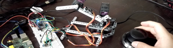
You’ve built the perfect robotic arm. How do you drive it? If you are [angrymop] you interface a 3D mouse from 3DConnexion via a few microcontroller boards. The Spacenavigator mouse is a staple anywhere professional CAD people are working, and it looks like it is a natural fit for a robot arm.
According to [angrymop], the Raspberry Pi can read the mouse’s commands via /dev/hidraw (that’s the raw human interface device). Each motion generates two lines of output. Each line has a unique identifying byte and values corresponding to the axis positions.
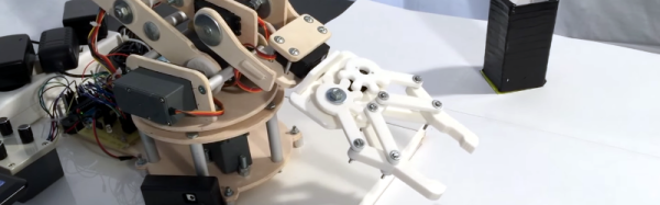
The Raspberry Pi then uses an SPI interface to talk to an ARM microcontroller and that drives the servos. The arm (the robot arm, not the processor) itself is well done, made from Lego Technic parts and common RC servos. Not that this is the most amazing thing we’ve ever seen built from Technic, but it is still pretty impressive.
You have to wonder if other 3D controllers might be useful for controlling robot arms or how the Spacenavigator would do controlling a bigger, more capable arm. Then again, maybe this arm would be the right size to build something inspired by Escher.