Persistence Pays In TI-99/4A Cassette Tape Data Recovery

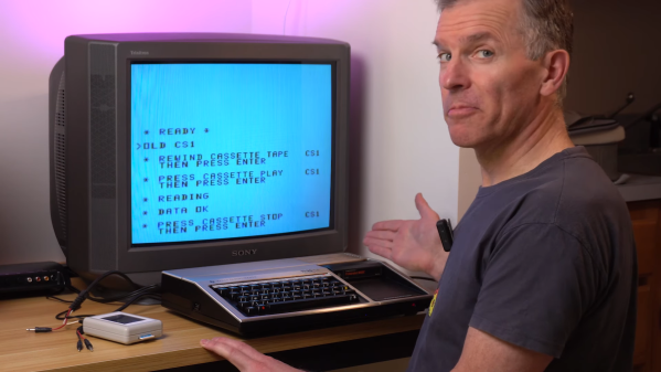
In the three or four decades since storing programs on audio cassettes has been relevant, a lot of irreplaceable personal computing history has been lost to the ravages of time and the sub-optimal conditions in the attics and basements where tapes have been stored. Luckily, over that time we’ve developed a lot of tools and techniques that might make it possible to recover some of these ancient treasures. But as [Noel] shows us, recovering data from cassette tapes is a tricky business.

His case study for the video below is a tape from a TI-99/4A that won’t load. A quick look in Audacity at the audio waveform seems to show the problem — an area of severely attenuated signal. Unfortunately, no amount of boosting and filtering did the trick, so [Noel] had to dig a bit deeper. It turns out that the TI tape interface standard, with its redundant data structure, was somewhat to blame for the inability to read this particular tape. As [Noel] explains, each 64-bit data record is recorded to tape twice, along with a header and a checksum. If neither record decodes correctly, then tape playback just stops.

Luckily, someone who had already run into this problem spun up a Windows program to help. CS1er — our guess would be “Ceaser” — takes WAV file input and loads each record, simply flagging the bad ones instead of just bailing out. [Noel] used the program to analyze multiple recordings of the same data and eventually got enough good records to reassemble the original program, a game called Dogfight — or was it Gogfight? Either way, he managed to get most of the data off the tape, and since it was a BASIC program, it was pretty easy to figure out the missing bytes by inspection.

[Noel]’s experience will no doubt be music to the ears of the TI aficionados out there. Of which we’ve seen plenty, from the TI-99 demoscene to running Java on one, and whatever this magnificent thing is.

Continue reading “Persistence Pays In TI-99/4A Cassette Tape Data Recovery”

Trouble Flashing Your ESP8266? Meet DIO And QIO

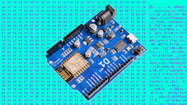
[Pete] was building a hot tub controller, using a WEMOS board based on the venerable ESP8266. After assembly, the board was plugged into USB and [Pete] hit the flash button. No dice. Investigation with some terminal software indicated a checksum error.

Assuming the board was dead, [Pete] grabbed another — and suffered the same problem.  The WEMOS boards wouldn’t program, but other boards had no issues. Sensing that something may be amiss, further research was in order. A forum post turned up discussing different programming modes for the ESP8266.

It turns out that there are different types of flash used with the ESP8266, and the correct programming mode must be selected for a given hardware setup. These modes are known as DIO and QIO, meaning “dual IO” and “quad IO” respectively. This refers to the number of IO line used to talk to the flash memory. There are also further modes, known as DOUT and QOUT. It’s important to identify the modes supported by the flash chip on board, by looking at the datasheet. Obviously this can be difficult on some pre-built modules, so experimentation is the key here.

With the wrong mode selected, writes to the flash will fail, and reading back will turn up a checksum error. It’s a simple matter of changing a line in the make file and trying different modes, to see which one works. This forum post has a more in-depth coverage of the issue. 

By choosing different flash memory parts and selecting the DIO or DOUT modes, it’s actually possible to free up more GPIO pins as well. This knowledge is handy when optimizing ESP8266 designs for memory speed or maximum IO flexibility. It’s a good lesson that it always pays to look at the datasheet to get the best out of your parts.

In Which Robots Fight The Console Wars

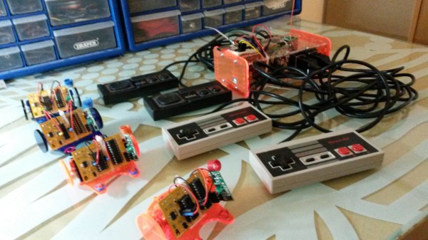
Though the names have changed over the years, the console wars wage on. [moop] must have been feeling nostalgic for the NES vs. SEGA days when he started his current project, Foobot, which is a tabletop football (soccer) game played by robots that are controlled with classic NES and SEGA controllers.

Each team has two robots that tool around on laser-cut perspex wheels attached directly to 16,000RPM motors. An SN754410 controls the motors, and each robot has an ATtiny2313 brain. They all communicate with a single transmitter over their 433MHz 1402 radio receiver modules. To avoid collisions, [moop] used a packet system, wherein each robot has an ID. The messages all contain a robot ID, message payload, and checksum. The robots ignore messages addressed to others, and any message with an invalid checksum.

[moop] has made everything available on his github, including the PCB layouts and CAD files for the robot chassis and transmitter case. Watch them battle it out after the break. If the Foobots have riled you up about vintage gaming, check out these sweet arcade hacks.

Continue reading “In Which Robots Fight The Console Wars”

Cracking Weather Station Checksum

[BaronVonSchnowzer] is spinning up some home automation and settled on an inexpensive ambient temperature sensor which is sold to augment the data a home weather station collects. He found that the RF protocol had been reverse engineered and will use this information to harvest data from a sensor in each room. In true hacker fashion, he rolled his own advances out to the Internet so that others may benefit. Specifically, he reverse engineered the checksum used by the Ambient F007TH.

He got onto this track after trying out the Arduino sketch written to receive the sensor’s RF communications. One peculiar part of the code turned out to be a filter for corrupt messages as the protocol’s checksum hadn’t yet been worked out. Figuring out how the checksum byte owrks wasn’t an easy process. The adventure led him to dump 13k samples into a spreadsheet to see if sorting similar sets of 5-byte message and 1-byte checksum would shed some light on the situation. The rest of the story is some impressive pattern matching that led to the final algorithm. Now [BaronVonSchnowzer] and anyone else using these modules can filter out corrupt data in the most efficient way possible.

BIOS Password Cracking

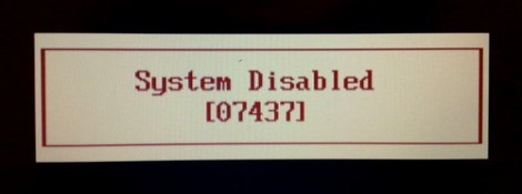
[Dogbert] took a look at the security that goes into BIOS passwords on many laptops. He starts off with a little background about how the systems work. People are bound to forget their passwords, so when you enter a wrong one three times in a row you get a message similar to the one above that locks you out until all power is removed from the system (then you get three more tries). But check out that five-digit number in the picture. That’s a checksum of the password. Some BIOS versions display it automatically, some require you to hold down a certain key during POST, but it’s the pivotal data needed to crack the password.

[Dogbert’s] post doesn’t go into verbose detail about the algorithms he uses to brute force the passwords. But he has posted the Python scripts he uses to do so. Learning how to generate the passwords based on the checksum is as simple as studying the code, which is often the best way to learn.

Subway Hacker Speaks


Popular Mechanics has an interview with [Zach Anderson], one of the MIT hackers that was temporarily gagged by the MBTA. The interview is essentially a timeline of the events that led up to the Defcon talk cancellation. [Zach] pointed out a great article by The Tech that covers the vulnerabilities. The mag stripe cards can be easily cloned. The students we’re also able to increase the value of the card by brute forcing the checksum. There are only 64 possible checksum values, so they made a card for each one. It’s not graceful, but it works. The card values aren’t encrypted and there isn’t an auditing system to check what values should be on the card either. The RFID cards use Mifare classic, which we know is broken. It was NXP, Mifare’s manufacturer, that tipped off the MBTA on the actual presentation.