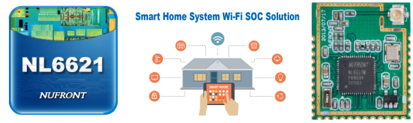
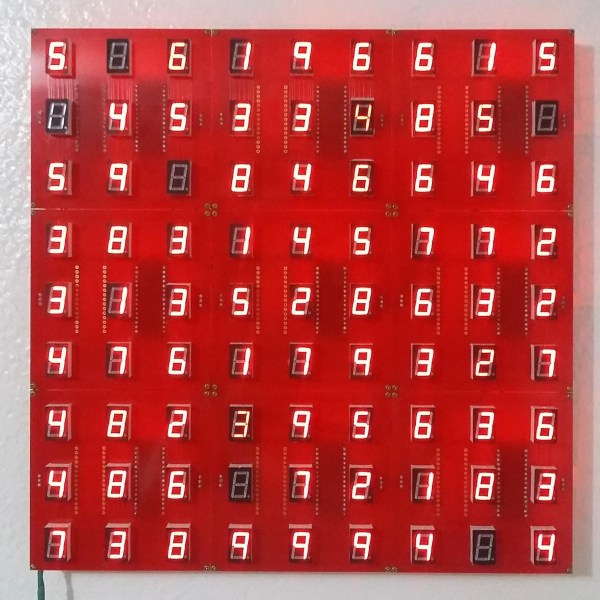
We’ve seen rumors floating around the Twittersphere about a new integrated microprocessor and WiFi SOC: the NL6621 from Nufront. Details are still scarce, but that doesn’t seem to be because the chip is vaporware: you could buy modules on Taobao.com and eBay right now for between two-and-a-half and three bucks, and Nufront’s website says they’ve produced a million modules since 2013.
The NL6621 WiFi SOC is powered by a 160 MHz ARM Cortex-M3 with 448 KB of RAM, and everything else is integrated in the SOC. The module has 32 GPIOs, SPI, I2C, I2S digital audio, and most of the peripherals that you’d expect. They say they have a completely open source SDK, but we can’t find a link to it anywhere. An English-language forum has sprung up in anticipation of the next new thing, and they say that they’ve contacted Nufront about the SDK, so that’s probably as good a place as any to lurk around if you’re interested. With an ARM core, it shouldn’t be long before someone gets GCC working on these things anyway.
It’s also worth noting that we’ve announced ESP8266 killers before, and it hasn’t come to pass. The mixture of community and official support that (eventually) came out of Espressif seems to be the main factor determining the ESP8266’s success, and we don’t see that yet with the NL6621. So take the question mark in the title seriously, but if this turns out to be the next big thing, remember where you heard it first, ok?
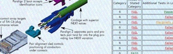
Though we’ve never used their cables, [Blue Jeans Cable] out of Seattle, WA sure does seem to take the black art of cable manufacture seriously. When they read the Cat 6 specification, they knew they couldn’t just keep building the cables the way they used to. So they did some research and purchased a Fluke certification tester for a measly 12,000 US dollars. While they were purchasing the device, they ran across an interesting tidbit in the fluke knowledge base. Fluke said that 80% of the consumer Cat 6 cables they tested didn’t begin to meet the Cat 6 specification.
This is the part where [Blue Jeans Cable] earns our respect; like good scientists, they set out to replicate Fluke’s results. Sure enough, 80% of the Cat 6 cables they tested from big box stores etc. failed the specification. More surprising, many of them didn’t even pass the Cat 5e specification. [Blue Jeans Cable] asserts that this is possible because the Ethernet cable specification is policed via the honor system, allowing manufacturers to be fairly brazen about what they label as Cat 6.
Despite tuning my extruder steps perfectly, and getting good results instantly on larger prints. I was still having a ton of trouble with smaller parts. PLA is the favored printing material for its low odor, low warping, and decent material properties. It also has many downside, but it’s biggest, for the end user, lies in its large glass transition temperature range. Like all thermoplastics, it shrinks when it cools, but because of this large range, it stays expanded and, getting deep into my reserve of technical terms, bendy for a long time. If you don’t cool it, the plastic will pile up in its expanded state and deform.
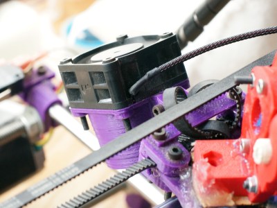
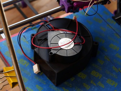
The old cooling fan on my trusty and thoroughly battered Prusa i2.
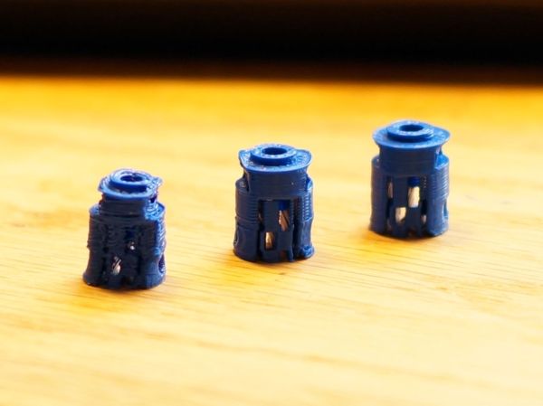
I am working on a project that needs a tiny part, pictured above. The part on the left is what I was getting with my current cooling set-up and temperature settings. It had very little semblance with the CAD file that brought it into this world.
The bond between layers in a 3d print occurs when the plastic has freshly left the nozzle at its melting point. Almost immediately after that, the plastic crosses from the liquid state into a glass state, and like pressing two pieces of glass together, no further bonding occurs. This means that in order to get a strong bond between the print layers, the plastic has to have enough thermal mass to melt the plastic below it. Allowing the polymer chains to get cozy and hold hands. Nozzle geometry can help some, by providing a heat source to press and melt the two layer together, but for the most part, the fusing is done by the liquid plastic. This is why large diameter nozzles produce stronger parts.
What I’m getting at is that I like to run my nozzle temperature a little hotter than is exactly needed or even sensible. This tends to produce a better bond and sometimes helps prevent jamming (with a good extruder design). It also reduces accuracy and adds gloopiness. So, my first attempt to fix the problem was to perhaps consider the possibility that I was not 100% right in running my nozzle so hot, and I dropped the temperature as low as I could push it. This produced a more dimensionally accurate part, but a extraordinarily weak one. I experimented with a range of temperatures, but found that all but the lowest produced goopy parts.
After confirming that I could not get a significant return on quality by fine tuning my temperature, I reduced the speed of the nozzle by a large percentage. By reducing the speed I was able to produce the middle of the three printed parts shown in the opening image. Moving the nozzle very slowly gave the ambient air and my old cooling fan plenty of time to cool the part. However, what was previously a five minute part now took twenty minutes to print. A larger part would be a nightmare.
This will do.
So, if I can’t adjust the temperature to get what I want, and I can adjust the speed; this tells me I just need to cool the part better. The glass state of the plastic is useless to me for two reasons. One, as stated before, no bonding occurs. Two, while the plastic remains expanded and bendy, the new layer being put down is being put down in the wrong place. When the plastic shrinks to its final dimension is when I want to place the next layer. Time to solve this the traditional way: overkill.
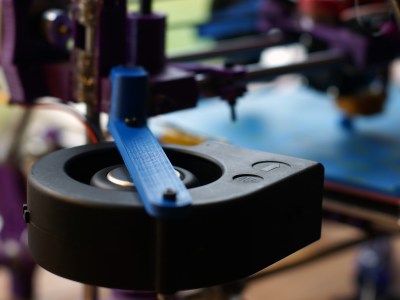
A while back my friend gifted me a little squirrel cage fan he had used with success on his 3d printer. Inspired by this, I had also scrounged a 12v, 1.7A fan from a broken Power Mac G5 power supply. When it spins up I have to be careful that it doesn’t throw itself off the table.
I should have added a rib to this bracket, this fan is heavy!
I printed out mounts for the fans. The big one got attached to the Z axis, and the little one rides behind the extruder. I fired up the gcode from before and started to print, only to find that my nozzle stopped extruding mid way. What? I soon discovered I had so much cooling that my nozzle was dropping below the 160C cold extrusion cut-off point and the firmware was stopping it from damaging itself. My heated bed also could no longer maintain a temperature higher than 59C. At this point I felt I was onto something.
I wrapped my extruder in fiberglass insulation and kapton tape, confidently turned the nozzle temperature up, set the speed to full, and clicked print. With the addition of the overkill cooling I was able to get the part shown to the right in my three example prints. This was full speed and achieved full bond. Not bad! Thus concludes this chapter in my adventures with cooling. I was really impressed by the results. Next I want to try cooling ABS as it prints. Some have reported horrible results, others pretty good ones, I’m interested. I also wonder about cooling the plastic with a liquid at a temperature just below the glass state as it is deposited. Thoughts?
Security researchers can be a grim crowd. Everything, when looked at closely enough, is insecure at some level, and this leads to a lot of pessimism in the industry. So it’s a bit of a shock to see a security report that’s filled with neither doom nor gloom.
We’d previously covered Somerset Recon’s initial teardown of “Hello Barbie” and were waiting with bated breath for the firmware dump and some real reverse engineering. Well, it happened and basically everything looks alright (PDF report). The Somerset folks desoldered the chip, dumped the flash ROM, and when the IDA-dust settled, Mattel used firmware that’s similar to what everyone else uses to run Amazon cloud service agents, but aimed at the “toytalk.com” network instead. In short, it uses a tested and basically sound firmware.
The web services that the creepy talking doll connected to were another story, and were full of holes that were being actively patched throughout Somerset’s investigation, but we were only really interested in the firmware anyway, and that looked OK. Not everything is horror stories in IoT security. Some stories do have a happy ending. Barbie can sleep well tonight.
The reports of the death of the VGA connector are greatly exaggerated. Rumors of the demise of the VGA connector has been going around for a decade now, but VGA has been remarkably resiliant in the face of its impending doom; this post was written on a nine-month old laptop connected to an external monitor through the very familiar thick cable with two blue ends. VGA is a port that can still be found on the back of millions of TVs and monitors that will be shipped this year.
This year is, however, the year that VGA finally dies. After 30 years, after being depreciated by several technologies, and after it became easy to put a VGA output on everything from an eight-pin microcontroller to a Raspberry Pi, VGA has died. It’s not supported by the latest Intel chips, and it’s hard to find a motherboard with the very familiar VGA connector.
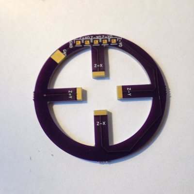
Recently I’ve been getting curious about interesting PCB shapes. In the past I’ve always used simple Polygons, perhaps rounding out the corners to make the design a little more aesthetically pleasing. The board to the right was my introduction to the possibilities of oddly shaped boards. It’s designed to couple with a piezo buzzer (used as an actuator). I’ve been planning to have it fabricated out of FPC (Flexible Printed Circuits), but with fabrication being so cheap I sent it to OSHPark to see what they’d make of it. OSHPark doesn’t have hard specs around internal routing, but in my experience they’re up to try anything (and they’re quality is always great). The width of the prongs on the PCB shown is 5mm. I figured it was a risk, and that it was likely the FR4 could break, but it came back great!
This has led me to the realization that my boards could look much more exciting than they do currently, and that our highly optimized modern PCB fabrication process provides a lot of room for experimentation. This article will discuss some of the options available when creating non-traditional PCBs.
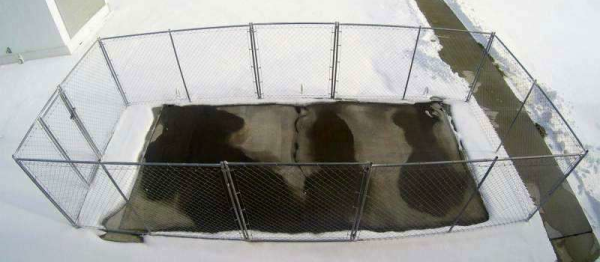
A few days ago we shared a project about building an epic snow-melting system right into your driveway. But for obvious reasons, it’s not that easy to do — or cheap. But [Chris Tuan], an engineering professor at the University of Nebraska thinks he can change that.
He’s created his own special formula for conductive concrete. Which means you can turn the concrete into a resistive heat load. And this isn’t just a university research project that is going nowhere; it’s actually being trialed by the FAA for use in airports . There is a patch of it in Omaha undergoing testing right now.
And it’s actually not that complex. It consists of a mixture of 20% steel shavings and carbon particles, in a regular run-of-the-mill concrete. Apparently, this is enough to cause the entire patch of concrete to become conductive, meaning if you pump enough juice through it — it’d definitely melt some ice on top.