There are several important decisions you make in your life: Coke or Pepsi; vi or emacs; PC or Mac. But, lately, you need to pick a battery ecosystem for your tools. DeWalt? Black & Decker? Or just cheapies from Harbor Freight? But what happens when your vendor of choice changes their batteries? That’s the situation [jleslie48] found when a DeWalt 14.4V battery died. All the new tools require 18V batteries, so buying an old battery for one tool didn’t make sense. Time to literally hack the old tool to accept the new battery.
Presumably, nothing in the drill will mind the higher voltage. It is all a matter of mechanics and nothing a Dremel tool won’t fix. Since the tool was old and the 18V batteries relatively new, [jleslie48] decided to limit modifications to the tool only leaving the batteries intact for use with the newer tools.
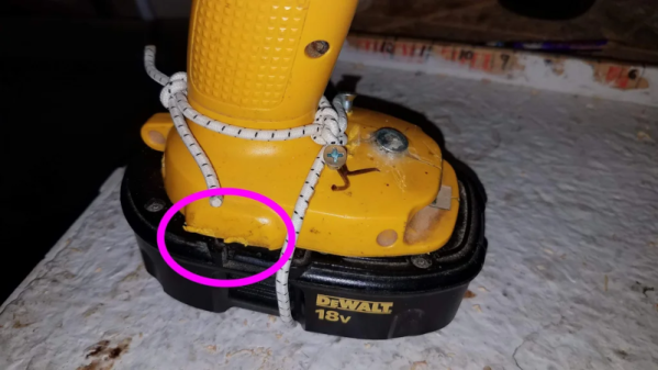
The only problem once you remove the pins and clips that interfere with the battery fit, it won’t actually stay on the drill. We might have turned to duct tape or zip ties, but bungee cord works, too, as you can see in the finished product.
Honestly, though, the bungee is good because you can stretch it to remove the battery for charging. We might have just cannibalized the drill for its motor, but next time you have a tool with no battery, it might be worth looking to see if you could modify the tool.
Bungees are great for robots, too. Or, you can lay siege on your neighbors.