These cheap Chinese-built programmable power supplies are nothing new, we’ve been using them for years. They’re not particularly good power supplies, since current feedback is in software, but for some tasks they’re a great fit and you can’t argue with the price. Alternative firmware projects have also been a thing for a while too, but none we’ve seen have been quite as capable and polished as this latest DPS firmware project by [Profi-max.] We’ve not come across the source code yet, but at least the binary image is freely downloadable.
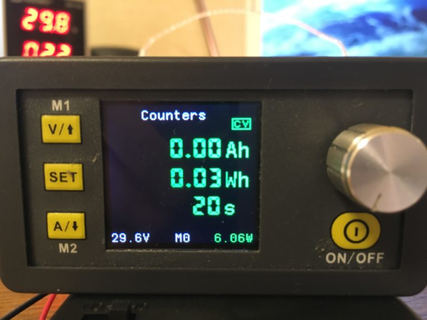
The firmware has some interesting features, such as programmable pre-sets intended for battery charging applications. In fact, there is a dedicated battery charge mode screen. We want to warn, however, that charging lithium ion batteries with this might not be at all wise, not in the least because of a lack of protection hardware in place. It would be very easy to destroy the unit or overheat a battery this way! However, if you must do this, there are a few features to help you out, such as a handy ‘counters’ screen showing approximate charge delivered.
Remote programmability is, as usual, via the easily hacked in serial port, with firmware support for Bluetooth serial modules if wired USB serial doesn’t suit. For those who like to mount things differently, the screen can be rotated by holding a key on power-up, or if you hook up a MPU6050 accelerometer/gyro module it will even do it automatically!
To update a stock DPS unit, the only requirements are access to an ST-Link compatible programmer dongle, to target the STM32 SWD programming interface, and the STM32CubeProgrammer utility. Open source alternatives to that are also available, stlink comes to mind as a good option. Once you have the module PCB popped out of its plastic casing, only three wires need tacking onto a handy set of pads to complete the connection to the programmer dongle. Pretty simple stuff.
If you’re looking for a similar project, with source immediately available, then checkout the OpenDPS project we covered a few years ago, and if you’re thinking of going crazy, building a DIY open source electronics lab, we got you covered.