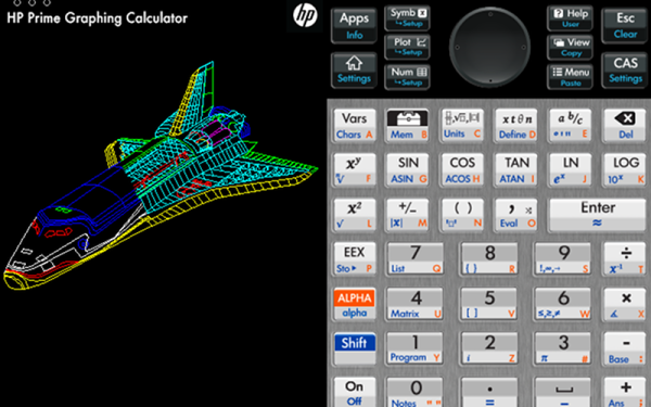
Well-Protected USB Power Strip Makes It Easy To Plug In

When we get a new device these days, somewhere in the package is likely to be a wall-wart USB power supply. We look for a place to plug in the little switch-mode dongle, rearrange a few plugs in the mains power strip, and curse its designers for the overly cozy outlet spacing. And all the while that USB-A plug on the power supply cable taunts us with its neat, compact form factor. If only there were a USB power strip.

Unwilling to suffer such indignity any longer, [Scott M. Baker] took matters into his own hands and designed this USB power distribution system. We were surprised to hear that he was unable to find a commercial USB power strip, but even if he had, it likely wouldn’t have had the bells and whistles that he added to his. The circuit went through a couple of revs, but each was focused on protection of the connected USB devices. He included both overcurrent protection, in the form of an electronic fuse built around a TPS2421 hot-swap controller, and overvoltage protection using a crowbar circuit with the usual zener-SCR arrangement. There’s also a transient voltage suppression diode to keep any inductive spikes at bay. Interestingly, each USB outlet has all these protections – it’s not just one protected bus feeding a bunch of USB outlets in parallel, but individual modules with all the circuitry. The modules are gangable and live inside a laser-cut acrylic case. The video below shows the design and build process in some detail.

We have to say that we always learn a lot about circuit design from [Scott]’s projects. You may recall his custom Atari 2600 controller or his dual-port memory retro game console, both interesting and instructive builds in their own right.

Continue reading “Well-Protected USB Power Strip Makes It Easy To Plug In”

This Home Made Power Hacksaw Cuts Quick And Clean

If you’re cutting metal in the workshop, you’re likely using a table-mounted cutoff saw, or perhaps a bandsaw for finer work. The power hacksaw is an unwieldy contraption that looks and feels very old fashioned in its operation. Despite the drawbacks inherent in the design, [Emiel] decided to build one that operates under drill power, and it came out a treat.

The build uses a basic battery powered drill as its power source. This is connected to a shaft which rotates a linkage not dissimilar to that seen on steam locomotives, but in reverse. The linkage in this case is turning the rotational motion of the drill into linear motion of the hacksaw, which moves along a metal rail, guided by a 3D printed bearing.

With a body of plywood and plastic moving parts, this might not be your tool of choice for high-volume, fast paced work. However, as [Emiel] notes, it’s faster than doing it by hand, and it was a fun build that by and large, used what was already lying around the workshop. It’s not the first time we’ve seen a powered hacksaw use 3D printed parts, either. Video after the break.

Continue reading “This Home Made Power Hacksaw Cuts Quick And Clean”

Test PCBs On A Bed Of Nails

While it might be tempting to start soldering a circuit together once the design looks good on paper, experience tells us that it’s still good to test it out on a breadboard first to make sure everything works properly. That might be where the process ends for one-off projects, but for large production runs you’re going to need to test all the PCBs after they’re built, too. While you would use a breadboard for prototyping, the platform you’re going to need for quality control is called a “bed of nails“.

This project comes to us by way of [Thom] who has been doing a large production run of circuits meant to drive nixie tubes. After the each board is completed, they are laid on top of a number of pins arranged to mate to various points on the PCB. Without needing to use alligator clamps or anything else labor-intensive to test, this simple jig with all the test points built-in means that each board can be laid on the bed and tested to ensure it works properly. The test bed looks like a bed of nails as well, hence the name.

There are other ways of testing PCBs after production, too, but if your board doesn’t involve any type of processing they might be hard to implement. Nixie tubes are mostly in the “analog” realm so this test setup works well for [Thom]’s needs.

Recycled Piano Becomes Upcycled Workbench

Pianos are free, in case you’re not hip to the exciting world of musical instrument salvage. Yes, the home piano, once the pinnacle of upper middle class appreciation of the arts, is no longer. The piano your great aunt bought in 1963 is just taking up space, and it’s not like the guy on Craigslist giving away a free piano has a Bösendorfer.

It’s out of this reality of a surplus of cheap used pianos that [luke] built a new desk. He got it a while ago, but after getting it into his house, he realized it was too old to be tuned anymore. Or at least it was uneconomical to do so. This piano became a workbench, but after a while [luke] wanted something with a little more storage.

The process of converting this piano to a desk began with taking a few photos and putting them into Fusion 360. A series of panels and brackets were modeled in box jointed plywood, and the entire thing was cut out of 6mm Baltic birch plywood at the Vancouver Hack Space.

There are a few nice features that make this desk a little better than an Ikea special. There’s a Raspberry Pi mounted to the shelves, because the Pi still makes a great workbench computer. There’s a power supply, and hookups for 12 V, 5 V, and 3.3 V from an ATX power supply. This is controlled with an awesome antique power switch mounted to the side of the piano. Slap a few coats of black paint on that, and [luke] has an awesome, functional workbench that also has out-of-tune sympathetic strings. Not bad.

You can check out the entire build video below. Thanks [Jarrett] for sending this one in.

Continue reading “Recycled Piano Becomes Upcycled Workbench”

A Science Lab In Your Pocket?

Since even the cheapest phone or computer now has plenty of horsepower, there’s been a move to create instruments that can do everything, using a reasonably simple front end and crunching data back on the host device. This is one of those tasks that seems easy, but doing it well turns out to be a lot of effort. One we recently noticed was Pocket Science Lab — a board that connects to your PC or Android phone and provides an oscilloscope, a logic analyzer, a wave generator, a power supply, a multimeter, and a few odd items such as an accelerometer, barometer, compass, and lux meter. The cost is about $65, so it isn’t a big investment. But what can it do? Read on, or you can watch the video below from Geekcamp Singapore.

The datasheet shows a reasonable device, although nothing amazing. The oscilloscope has 4 channels but only does 2 MSPS, so assuming the front end can handle it, you might visualize 1 MHz sine waves. There’s also a 12-bit voltmeter, three 12-bit power supplies with different ranges, a 4 MHz 4 channel logic analyzer, two sine or triangle wave generators, 4 PWM outputs, and the ability to measure capacitance. Finally, there’s a frequency counter that’s good to 16 MHz.

Continue reading “A Science Lab In Your Pocket?”

How To Make Your Own Springs For Extruded Rail T-Nuts

Open-Source Extruded Profile systems are a mature breed these days. With Openbuilds, Makerslide, and Openbeam, we’ve got plenty of systems to choose from; and Amazon and Alibaba are coming in strong with lots of generic interchangeable parts. These open-source framing systems have borrowed tricks from some decades-old industry players like Rexroth and 80/20. But from all they’ve gleaned, there’s still one trick they haven’t snagged yet: affordable springloaded T-nuts.

I’ve discussed a few tricks when working with these systems before, and Roger Cheng came up with a 3D printed technique for working with T-nuts. But today I’ll take another step and show you how to make our own springs for VSlot rail nuts.

Continue reading “How To Make Your Own Springs For Extruded Rail T-Nuts”

DIY Vacuum Table Enhances PCB Milling

CNC milling a copper-clad board is an effective way to create a PCB by cutting away copper to form traces instead of etching it away chemically, and [loska] has improved that process further with his DIY PCB vacuum table. The small unit will accommodate a 100 x 80 mm board size, which was not chosen by accident. That’s the maximum board size that the free version of Eagle CAD will process.

When it comes to milling PCBs, double-sided tape or toe clamps are easy solutions to holding down a board, but [loska]’s unit has purpose behind its added features. The rigid aluminum base and vacuum help ensure the board is pulled completely flat and held secure without any need for external fasteners or adhesives. It’s even liquid-proof, should cutting fluid be used during the process. Also, the four raised pegs provide a way to reliably make double-sided PCBs. By using a blank with holes to match the pegs, the board’s position can be precisely controlled, ensuring that the back side of the board is cut to match the front. Holes if required are drilled in a separate process by using a thin wasteboard.

Milling copper-clad boards is becoming more accessible every year; if you’re intrigued by the idea our own [Adil Malik] provided an excellent walkthrough of the workflow and requirements for milling instead of etching.