Thermal cameras are one of those tools that we all want, but just can’t justify actually buying. You don’t really know what you would do with one, and when even the cheap ones are a couple hundred dollars, it’s a bit out of the impulse buy territory. So you just keeping waiting and hoping that eventually they’ll drop to the price that you can actually own one yourself.
 Well, today might be the day you were waiting for. While it might not be the prettiest build, we think you’ll agree it can’t get much easier than what [vvkuryshev] has put together. His build only has two components: a Raspberry Pi and a thermal camera module he picked up online for about $80 USD. There isn’t even any wiring involved, the camera fits right on the Pi’s GPIO header.
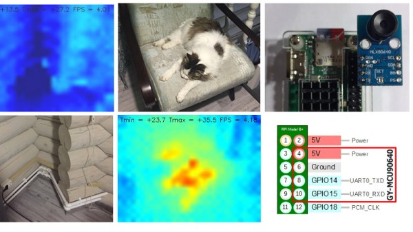
Of course, you probably wouldn’t be seeing this on Hackaday if all he had to do was just buy a module and solder it to the Pi’s header. As with most cheap imported gadgets, the GY-MCU90640 module that [vvkuryshev] bought came with some crusty Windows software which wasn’t going to do him much good on the Raspberry Pi. But after going back and forth a bit with the seller, he was able to get some documentation for the device that put him on the right track to writing a Python script which got it working under Linux.
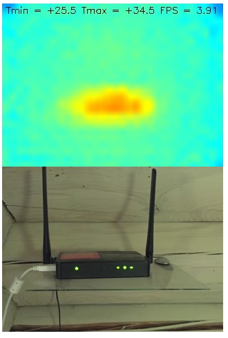
The surprisingly simple Python script reads a frame from the camera four times a second over serial and run it through OpenCV. It even adds some useful data like the minimum and maximum temperatures in the frame to the top of the image. Normally the script would output to the Pi’s primary display, but if you want to use it remotely, [vvkuryshev] says he’s had pretty good luck running it over VNC. In fact, he says that with a VNC application on your phone you could even use this setup on the go, though the setup is a bit awkward for that in its current incarnation.
This isn’t the first DIY thermal camera build we’ve seen, and it isn’t even the first one we’ve seen that leveraged a commercially available imaging module. But short of buying a turn-key camera, we don’t see how it could get any easier to add heat vision to your bag of tricks.