When you’re a high schooler who built a semiconductor fab in your garage, what’s next on your agenda? Why, adding a scanning electron microscope to your lab, naturally. How silly of you to ask.
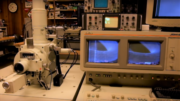
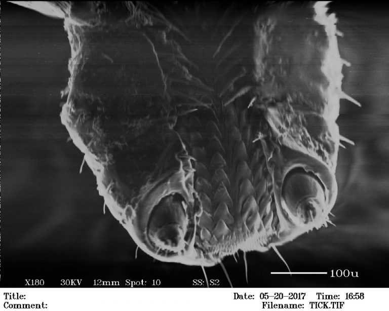 When last we stumbled across the goings on in the most interesting garage in New Jersey, [Sam Zeloof] was giving a tour of his DIY semiconductor fabrication lab and showing off some of the devices he’s made there, including diodes and MOSFETs. As impressive as those components are, it’s the equipment he’s accumulated that really takes our breath away. So adding an eBay SEM to the mix only seems a natural progression, and a good reason to use some of the high vacuum gear he has. The video below shows [Sam] giving a tour of the 1990s-vintage instrument and shows images of various copper-sputtered samples, including a tick, which is apparently the state bird of New Jersey.
SEM hacks are by no means common around here, but they’re not unheard of. [Ben Krasnow] has used his to image cutting tools and phonograph records in action, and there are a few homebrew SEMs kicking around too. But our hats are off to [Sam] for yet another acquisition and a great tutorial to boot.
Continue reading “Scanning Electron Microscope Adds To Already Impressive Garage Lab”