You never know what you might find in an arts and craft store. A relatively recent addition to crafting is automatic cutting machines like the Cricut and Cameo cutters. These are typically used to cut out shapes for scrapbooking, although they will cut or engrave almost anything thin. You can think of them as a printer with a cutting blade in place of the print head. [Mikeselectricstuff] decided to try a Cameo cutter to produce SMD stencils. The result, as you can see in the video below, is quite impressive.
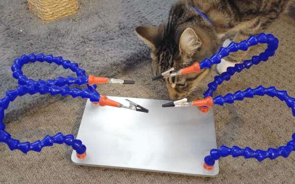
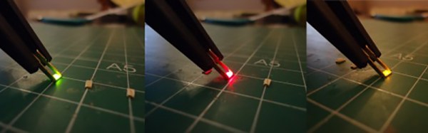
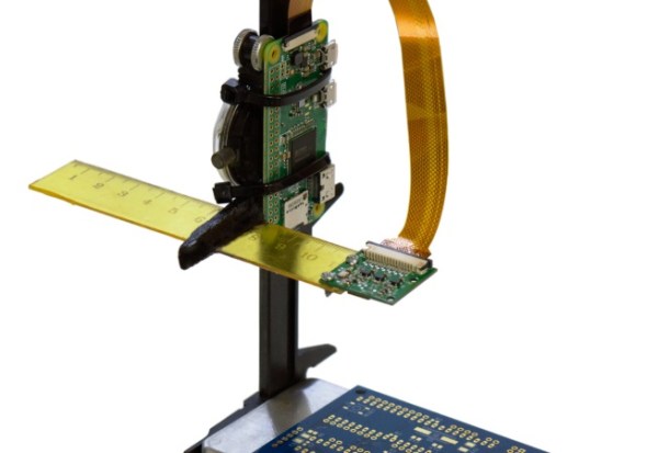
If you’ve ever wanted to do SMD soldering with a reflow oven, stencils are invaluable for putting solder paste on the board where you want it quickly. The board [Mike] has contains a boat-load (over 2,000) of LEDs and dropping solder on each pad with a syringe would be very time consuming (although he did do some touch up with a syringe).
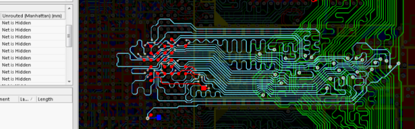
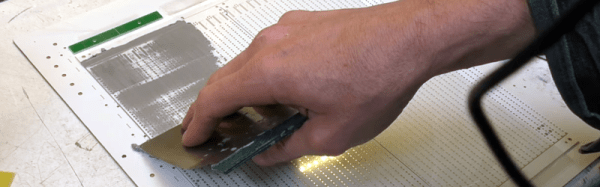
The board he’s using doesn’t have any extreme fine-pitched parts. However, he did some test patterns and decided he could get down to a finer pitch, especially with a little tweaking. However, the stencil he used didn’t need any changes. All he did was export the solder paste layer as a DXF and bring it straight into the Cameo software.
This isn’t the first time we’ve seen one of these cutters pressed into stencil service. You can also get some use out of your 3D printer.