Injection Molds: Aluminum Or Resin?

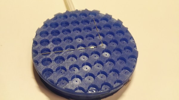
[JohnSL] and his friend both have injection molding machines. They decided to compare the aluminum molds they usually use with some 3D printed molds created with a resin printer. They used two different resins, one on each side of the mold. You can see a video of the results below.

One half of the mold used ordinary resin while the other side used a resin that is made to hold up to higher temperatures. As you might expect, the lower-temperature resin didn’t stand up well to molten plastic. However, the higher temperature resin did somewhat better. It makes sense, though, that an aluminum mold draws more heat out of the plastic which is helpful in the molding process.

The higher temperature — and more expensive — resin did seem to hold up rather well, though. Of course, this was just to test. In real life, you’d want to use the better resin throughout.

No surprise, the resin molds didn’t last nearly as long as a proper mold. After 70 shots, the mold was worn beyond what you’d want to use. So not necessarily something you’d want to use for a real production run, but it should be enough for a quick prototype before you go to the expense of creating a proper mold.

We wonder if there are some other tricks to get better results. A comment from [TheCrafsMan] suggests that clear resin UV cures better, and that might produce better results. In fact, there are a lot of interesting comments on the video from people who have varied experiences trying to do the same thing.

If nothing else, watching the mill cut through the aluminum around the 15-minute mark is always interesting to watch.  If you don’t already have an injection molding setup, you can always build one. We’ve seen more than one design.

Continue reading “Injection Molds: Aluminum Or Resin?”

Getting Serial Data Out Of An Old Spectrophotometer

[Jure Spiler] came into possession of an old spectrophotometer, which measures the absorbance and transmittance of light in a sample. Getting data out of the device was difficult, particularly as the model in question was an educational version missing some functionality. However, perseverance got the old machine talking happily to a PC.

After an earlier experiment with sniffing the signals being sent to the LCD, [Jure] did some more research. It turned out that a special expensive cable could hook up to the device’s parallel port and deliver serial data, for the low price of € 356 Euros. Now knowing a serial output was present, [Jure] was able to find the data stream desired.

Hooking up a logic analyzer to the “parallel port” on the machine revealed that the device would actually send serial data out over certain pins on the port. The trick that made it harder was that it was in Inverted RS232 form. Thus, all it took was a simple TTL inverter hooked up to a USB-TTL adapter to get the device talking to a modern PC.

With that achieved, [Jure] was able to whip up a simple VB6 program to collect data from the spectrometer and put it in a CSV file for further analysis. There’s even a program to graph the data right off the bat, making the scientific instrument easier and quicker to use than ever!

Oftentimes, old scientific hardware like this isn’t especially difficult to hack. It’s usually just hard enough to make busy scientists stump up the cash for the fancy adapters and cable, while being no match for the dedicated hacker!

A Water Leak Detector That Listens Carefully

Water leaks can be pernicious things. Even just a few drips per minute happening undetected inside a wall can cause major damage if left unrepaired for long enough. AquaPing is a new device that hopes to detect difficult-to-find water leaks with the aid of acoustic methods. 

The AquaPing is a so-called “stand-off” sensor that is intended to detect leaks at a distance, even if they are inside a wall. No contact is needed with the plumbing itself. Instead, the device detects the broadband high-frequency noise created when water leaks from a pipe under pressure.

It’s a method that’s best suited to leaks from cracks or loose fittings. These generate a characteristic hiss that can be picked up with signal analysis even if the noise itself is obscured to human perception by other noises in the area. However, leaks like a hole in a gutter or a dripping rusted-out water tank are best found by other methods, as they don’t create this same signature noise.

The device will soon be launched on CrowdSupply as a purchasable product, however the project is fully open source for those eager to dive in themselves. We’ve featured some other really creative leak detectors before, too! Video after the break.

Continue reading “A Water Leak Detector That Listens Carefully”

Active Signal Tracer Probe Has AGC

[Electronics Old and New] has a new version of one of his old projects. The original project was an active probe. He took what he learned building that probe and put it into a new probe design. He also added automatic gain control or AGC. You can see a video explanation of the design below. The probe is essentially a high-impedance input using a JFET that can amplify audio or demodulated RF signals, which is a handy device to have when troubleshooting radios.

The audio amplifier is a simple LM386 circuit. The real work is in the input stage and the new AGC circuit. Honestly, we’ve used the amplifier by itself for a similar function, although the raw input impedance of the chip is only about 50K and is less in many circuits that use a pot on the input. Having a JFET buffer and an RF demodulating diode is certainly handy. You’d think the AGC block would be in the audio stage. However, the design uses it ahead of the detector which is great as long as the amplifier can handle the RF frequency you are interested in. In this case, we think he’s mostly working on old tube AM radios, so the max signal is probably in the neighborhood of 1 MHz.

A similar device was a Radio Shack staple for many years

The module is made to amplify an electret microphone using a MAX9814 which has AGC. The module had a microphone that came off for this project. The datasheet doesn’t mention an upper frequency limit, but a similar Maxim part mentions its gain is greater than 5 at 600 kHz, so for the kind of signals this is probably used for, it should work well. We wondered if you could use the module and dispense with the JFET input. The chip probably has a pretty high input impedance, but the datasheet doesn’t give a great indication.

For years we used a signal tracer from Radio Shack which — if we could still find it — now has an LM386 inside of it after the original electronics failed decades ago. In those days, fixing an AM radio involved either using a device like this to find where you did and didn’t have a signal or injecting signals at different points in the radio. Two sides of the same coin. For example, if you could hear a signal at the volume control — that indicated the RF stages were good and you had a problem on the audio side. Conversely, if you injected a signal at the volume control, not hearing would mean the same thing. Once you knew if the problem was in the RF or AF side, you’d split that part roughly in half and repeat the operation until you were down to one bad stage. Of course, you could use signal generators and scopes, but in those days you weren’t as likely to have those.

Heathkit, of course, had their own version. It even had on of those amazing magic eye tubes.

Continue reading “Active Signal Tracer Probe Has AGC”

No Tool Left Behind With The Help Of Homemade Shadow Boards

Shadowed tool storage — where a tool outline shows at a glance what’s missing from storage — is a really smart way to keep your shop neat. They’re also super important for cases where a tool left behind could be a tragedy. Think, where’s-that-10-mm-socket-while-working-on-a-jet-engine? important. (It’s always the 10-mm socket.)

But just because shadow boards are smart, doesn’t mean they’re easy to make. That’s why [Scott Prince] came up with this semi-automated method for making toolbox shadow boards. The job of tracing around each tool on some sort of suitable material and cutting out the shapes seems straightforward, but the trick comes in organizing the outlines given the space available and the particular collection of tools.

[Scott]’s method starts with capturing images of each individual tool. He used a PiCam and a lightbox housed, strangely enough, in a storage bench; we’d love to hear the full story behind that, but pretty much any digital camera would do for the job. After compensating for distortion with OpenCV, cropping the images, and turning the image into a vector outline of the tool, [Scott] was left with the task of putting the tools into logical groups and laying them out sensibly. After tweaking the tool outlines and adding finger cutouts for easy pickup, [Scott] put his CNC router to work. He chose to use a high-density polyethylene product made by his employer, which looks fantastic, but MDF would work fine too.

We have to admit to a fair degree of toolbox envy now that we’ve seen what shadow boards can do. We’re a bit torn, though — [Zach Friedman]’s Gridfinity storage system has a lot going for it, too.

Tips For Winding Durable Coils With Nice, Flat Sides

[Drew Pilcher] needed durable, custom-wound coils with no core, and perfectly flat sides. Coils can be wound by hand, of course, but reliably creating perfect coils with thin wire and lots of layers requires some additional help. Happily, [Drew] shares his method for doing exactly that. Perhaps coming as no surprise, the key to repeatable, high-quality coils is good preparation and tools.

The most important part is the ability to rotate a spool for winding without having to take one’s hands off the workpiece. To accomplish this, a cheap, no-name power drill and foot pedal (made from the harvested trigger unit of the drill) forms the basis of [Drew]’s DIY winder. To make coils with precision, one must also count the number of turns. Thankfully, there is a simple solution for this; [Drew] used a cheap digital turn counter from Amazon. This economical device uses a magnet and sensor, so [Drew] simply stuck the magnet on the side of the drill’s chuck.

Careful winding and a liberal application of CA glue helps ensure good results.

The spool is what the wire gets wound around to form the coil, and it will need to be removed from the coil afterwards. To accomplish this, [Drew] uses a brass shaft, metal washers, and some plastic spacers. A light coating of grease on the spool surfaces helps ensure things come apart properly in the end.

To actually make the coil, [Drew] recommends some means of magnification, and a supply of CA glue. Wind the wire as cleanly and closely as possible, and apply CA glue during the process to secure things. It takes some practice, but really clean windings are possible if done correctly.

For thick coils with a lot of layers, the CA glue will hold things together well enough, but for smaller coils [Drew] likes to give them a final coating of two-part epoxy. After things are completely set, the spool is disassembled and the inner core is pushed out as gently as possible.

The result? A tightly-wound, durable coil with perfectly flat sides. It’s exactly the thing [Drew] needs for his upcoming coil gun project. How’s that work, you wonder? You can see the basics covered right here.

Balancing A Motor With An Oscilloscope

With all things in life, one must seek to achieve balance. That may sound a little like New Age woo-woo, but if you think it’s not literally true, just try tolerating a washing machine with a single comforter on spin cycle, or driving a few miles on unbalanced tires.

Anything that rotates can quickly spin itself into shrapnel if it’s not properly balanced, and the DIY power tools in [Matthias Wandel]’s shop are no exception. Recent upgrades to his jointer have left the tool a bit noisy, so he’s exploring machine vibrations with this simple but clever setup. Using nothing but a cheap loudspeaker and an oscilloscope, [Matthias] was able to characterize vibrations in a small squirrel-cage blower — he wisely chose to start small to validate his method before diving into the potentially dangerous jointer. There was quite a lot to be learned from the complex waveforms coming back from the transducer, analysis of which was greatly helped by the scope’s spectrum analyzer function. The video below shows the process of probing various parts of the blower, differentiating spectral peaks due to electrical noise rather than vibration, and actually using the setup to dynamically balance the fan.

We’d rate this as yet another handy shop tip from [Matthias], and we’ll be looking out for the analysis of his jointer. Want to do the same but you don’t have an oscilloscope? No problem — an earbud and Audacity might be all you need.

Continue reading “Balancing A Motor With An Oscilloscope”