One of the lost pleasures of our modern world is the experience of going shopping at a grocery store, a mall, or a drugstore, and finding this month’s electronics magazine festooned with projects that you might like to build. Sure, you can find anything on the Internet, but there’s something to be said about the element of surprise. Can any of those old projects still be of interest?
[Bettina Neumryr] thinks so. She has a hobby of finding old magazine projects and building them. Her most recent installment is a transistor tester from the June 1983 issue of Everyday Electronics.
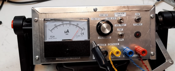
The tester was quite a neat job for 1983, with a neat case and a PC board. It measures beta and leakage. There’s an analog meter that can measure the collector current for a fixed base current (beta or hfe). Leakage is how much current flows between emitter and collector with the base turned off.
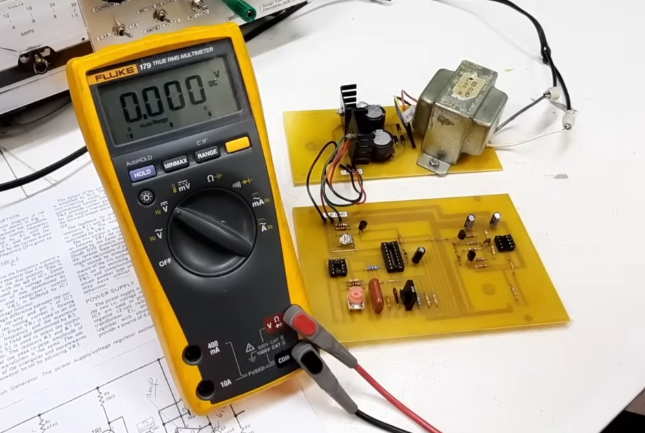
In 1983, we’d have loved to have a laser printer to do toner transfer for the PC board, but of course, that was unheard of in hobby circles of the day. The tester seemed to work right off the bat, although there was a small adjustment necessary to calibrate the device. All that was left was to put it in a period-appropriate box with some printed labels.
We loved the old electronics and computer magazines. Usually, when we see someone working on an old magazine project, it is probably not quite a literal copy of it. But either way is cool.