Engraving of Alexander Graham Bell's photophone, showing the receiver and its optics

Replica Of 1880 Wireless Telephone Is All Mirrors, No Smoke

If we asked you to name Alexander Graham Bell’s greatest invention, you would doubtless say “the telephone”; it’s probably the only one of his many, many inventions most people could bring to mind. If you asked Bell himself, though, he would tell you his greatest invention was the photophone, and if the prolific [Nick Bild] doesn’t agree he’s at least intrigued enough to produce a replica of this 1880-vintage wireless telephone. Yes, 1880. As in, only four years after the telephone was patented.

It obviously did not catch on, and is not the sort of thing that comes to mind when we think “wireless telephone”. In contrast to the RF of the 20th century version, as you might guess from the name the photophone used light– sunlight, to be specific. In the original design, the transmitter was totally passive– a tube with a mirror on one end, mounted to vibrate when someone spoke into the open end of the tube. That was it, aside from the necessary optics to focus sunlight onto said mirror. [Nick Bild] skips this and uses a laser as a handily coherent light source, which was obviously not an option in 1880. As [Nick] points out, if it was, Bell certainly would have made use of it.

Bell's selenium-based photophone receiver.
The photophone receiver, 1880 edition. Speaker not pictured.

The receiver is only slightly more complex, in that it does have electronic components– a selenium cell in the original, and in [Nick’s] case a modern photoresistor in series with a 10,000 ohm resistor. There’s also an optical difference, with [Nick] opting for a lens to focus the laser light on his photoresistor instead of the parabolic mirror of the original. In both cases vibration of the mirror at the transmitter disrupts line-of-sight with the receiver, creating an AM signal that is easily converted back into sound with an electromagnetic speaker.

The photophone never caught on, for obvious reasons — traditional copper-wire telephones worked beyond line of sight and on cloudy days–but we’re greatful to [Nick] for dredging up the history and for letting us know about it via the tip line. See his video about this project below.

The name [Nick Bild] might look familiar to regular readers. We’ve highlighted a few of his projects on Hackaday before.

Continue reading “Replica Of 1880 Wireless Telephone Is All Mirrors, No Smoke”

The host stands in his electronics lab with the image of four remote controls overlaid.

Introducing Infrared Remote Control Protocols

Over on his YouTube channel [Electronic Wizard] has released a video that explains how infrared (IR) remote controllers work: IR Remote Controllers protocol: 101 to advanced.

This diagram indicates how the 38 kHz carrier wave is used to encode a binary signal.This video covers the NEC family of protocols, which are widely used in typical consumer IR remote control devices, and explains how the 38 kHz carrier wave is used to encode a binary signal.  [Electronic Wizard] uses his Rigol DS1102 oscilloscope and a breadboard jig to sniff the signal from an example IR controller.

There is also an honorable mention of the HS0038 integrated-circuit which can interpret the light waves and output a digital signal. Of course if you’re a tough guy you don’t need no stinkin’ integrated-circuit IR receiver implementation because you can build your own!

Before the video concludes there is a brief discussion about how to interpret the binary signal using a combination of long and short pulses. If this looks similar to Morse Code to you that’s because it is similar to Morse Code! But not entirely the same, as you will learn if you watch the video!

Simple Antenna Makes For Better ESP32-C3 WiFi

We’ve seen tons of projects lately using the ESP32-C3, and for good reason. The microcontroller has a lot to offer, and the current crop of tiny dev boards sporting it make adding a lot of compute power to even the smallest projects dead easy. Not so nice, though, is the poor WiFi performance of some of these boards, which [Peter Neufeld] addresses with this quick and easy antenna.

There are currently a lot of variations of the ESP32-C3 out there, sometimes available for a buck a piece from the usual suspects. Designs vary, but a lot of them seem to sport a CA-C03 ceramic chip antenna at one end of the board to save space. Unfortunately, the lack of free space around the antenna makes for poor RF performance. [Peter]’s solution is a simple antenna made from a 31-mm length of silver wire. One end of the wire is formed into a loop by wrapping it around a 5-mm drill bit and bending it perpendicular to the remaining tail. The loop is then opened up a bit so it can bridge the length of the ceramic chip antenna and then soldered across it. That’s all it takes to vastly improve performance as measured by [Peter]’s custom RSSI logger — anywhere from 6 to 10 dBm better. You don’t even need to remove the OEM antenna.

The video below, by [Circuit Helper], picks up on [Peter]’s work and puts several antenna variants to further testing. He gets similarly dramatic results, with 20 dBm improvement in some cases. He does note that the size of the antenna can be a detriment to a project that needs a really compact MCU and tries coiling up the antenna, with limited success. He also did a little testing to come up with an optimal length of 34 mm for the main element of the antenna.

There seems to be a lot of room for experimentation here. We wonder how mounting the antenna with the loop perpendicular to the board and the main element sticking out lengthwise would work. We’d love to hear about your experiments, so make sure to ping us with your findings.

Continue reading “Simple Antenna Makes For Better ESP32-C3 WiFi”

Pluto’s Not A Planet, But It Is A Spectrum Analyzer

The RTL-SDR dongles get most of the love from people interested in software-defined radio, but the Pluto is also a great option, too. [FromConceptToCircuit] shares code to turn one of these radios into a spectrum analyzer that sweeps up to 6 GHz and down to 100 MHz. You can see a video of how it works below.

While it may seem that 100 MHz is a bit limiting, there’s plenty of activity in that range, including WiFi, Bluetooth, radio systems, both commercial and amateur, and even cell phones.

Continue reading “Pluto’s Not A Planet, But It Is A Spectrum Analyzer”

How Shrinking Feature Size Made Modern Wireless Work

If you’re living your life right, you probably know what as MOSFET is. But do you know the MESFET? They are like the faster, uninsulated, Schottky version of a MOSFET, and they used to rule the roost in radio-frequency (RF) silicon. But if you’re like us, and you have never heard of a MESFET, then give this phenomenal video by [Asianometry] a watch. In it, among other things, he explains how the shrinking feature size in CMOS made RF chips cheap, which brought you the modern cellphone as we know it.

The basic overview is that in the 1960s, most high-frequency stuff had to be done with discrete parts because the bipolar-junction semiconductors of the time were just too slow. At this time, MOSFETs were just becoming manufacturable, but were even slower still. The MESFET, without its insulating oxide layer between the metal and the silicon, had less capacitance, and switched faster. When silicon feature sizes got small enough that you could do gigahertz work with them, the MESFET was the tech of choice.

As late as the 1980s, you’d find MESFETs in radio devices. At this time, the feature size of the gates and the thickness of the oxide layer in MOSFETs kept them out of the game. But as CPU manufacturers pushed CMOS features smaller, not only did we get chips like the 8086 and 80386, two of Intel’s earliest CMOS designs, but the tech started getting fast enough for RF. And the world never looked back.

If you’re interested in the history of the modern monolithic RF ICs, definitely give the 18-minute video a watch. (You can skip the first three or so if you’re already a radio head.) If you just want to build some radio circuits, this fantastic talk from [Michael Ossmann] at the first-ever Supercon will make you an RF design hero. His secrets? Among them, making the most of exactly these modern everything-in-one-chip RF ICs so that you don’t have to think about that side of things too hard.

Thanks [Stephen] for the tip!

Continue reading “How Shrinking Feature Size Made Modern Wireless Work”

Pictures From A High Altitude Balloon

How do you get images downlinked from 30 km up? Hams might guess SSTV — slow scan TV — and that’s the approach [desafloinventor] took. If you haven’t seen it before (no pun intended), SSTV is a way to send images over radio at a low frame rate. Usually, you get about 30 seconds to 2 minutes per frame.

The setup uses regular, cheap walkie-talkies for the radio portion on a band that doesn’t require a license. The ESP32-CAM provides the processing and image acquisition. Normally, you don’t think of these radios as having a lot of range, but if the transmitter is high, the range will be very good. The project steals the board out of the radio to save weight. You only fly the PC board, not the entire radio.

If you are familiar with SSTV, the ESP-32 code encodes the image using Martin 1. This color format was developed by a ham named [Martin] (G3OQD). A 320×256 image takes nearly two minutes to send. The balloon system sends every 10 minutes, so that’s not a problem.

Of course, this technique will work anywhere you want to send images over a communication medium. Hams use these SSTV formats even on noisy shortwave frequencies, so the protocols are robust.

Hams used SSTV to trade memes way before the Internet. Need to receive SSTV? No problem.

What’s Wrong With This Antenna Tuner?

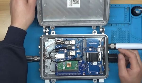
[Tech Minds] built one of those cheap automatic antenna tuners you see everywhere — this one scaled up to 350 watt capability. The kit is mostly built, but you do have to add the connectors and a few other stray bits. You can see how he did it in the video below.

What was very interesting, however, was that it wasn’t able to do a very good job tuning a wire antenna across the ham bands, and he asks for your help on what he should try to make things better.

Continue reading “What’s Wrong With This Antenna Tuner?”