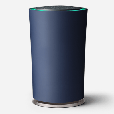
DNS Tunneling With An ESP8266

There’s a big problem with the Internet of Things. Everything’s just fine if your Things are happy to sit around your living room all day, where the WiFi gets four bars. But what does your poor Thing do when it wants to go out and get a coffee and it runs into a for-pay hotspot?

[Yakamo]’s solution is for your Thing to do the same thing you would: tunnel your data through DNS requests. It’s by no means a new idea, but the combination of DNS tunneling and IoT devices stands to be as great as peanut butter and chocolate.

DNS tunneling, in short, relies on you setting up your own DNS server with a dedicated subdomain and software that will handle generic data instead of information about IP addresses. You, or your Thing, send data encoded in “domain names” for it to look up, and the server passes data back to you in the response.

DNS tunneling is relatively slow because all data must be shoe-horned into “domain names” that can’t be too long. But it’s just right for your Thing to send its data reports back home while it’s out on its adventure.

Oh yeah. DNS tunneling may violate the terms and conditions of whatever hotspot is being accessed. Your Thing may want to consult its lawyer before trying this out in the world.

Wireless Weather Station

High schooler [Vlad] spent about a year building up his battery-operated, wireless weather station. Along the way, not only has he learnt a lot and picked up useful skills, but also managed to blog his progress.

The station measures temperature, humidity, pressure and battery voltage, and he plans to add sensors for wind speed, wind direction and rainfall soon. It is powered via a solar panel and can run on a charged battery for a full month. The sensor module transmits data to a remote receiver connected to a computer from where it is published to the internet. Barometric pressure is measured using the BMP180 and the DHT22 provides temperature and humidity values. The link between the transmit and receive sections uses a 433MHz Superhetrodyne RF Kit which gives [Vlad] a range of 50m. There’s an ATMega328 on the transmitter and receiver side. He’s taking measurements once every 12 minutes, and putting the micro controller in low power mode using the Rocket Scream Low Power Library. A 5W, 12V solar panel charges the 6V Lead Acid battery via a LM317 based charge circuit. This ensures the battery gets charged even when the solar panel is not receiving optimal radiation. One hour of sunlight provides enough charge to keep it going for 2 days. And a fully charged battery will keep it running for a full month even when there’s no sunlight.

The server software consists of two parts. The first pushes serial data to a mySQL database. This is written in Visual Studio C# using help from Oracle mySQL connector. The second part publishes the entries in the mySQL database to the web server. This is written in php, and uses  Libchart for graphing. He’s got the code, schematics, parts list and a lot of other information available for download on his blog. There’s a couple of items pending on his to-do list, so if you have any tips to offer post your comments below.

IR Remote For Smartphone Via Bluetooth Adapter

Quite often, the raison d’être for building a project is to learn and hone one’s skills. In which case it doesn’t matter if the end use seems a bit frivolous. [indiantinker] built BlueIR, a device to control Bluetooth A2DP devices using an archaic IR Remote using a BT-Aux Adapter.

Sounds convoluted? Let’s try again. He uses an old IR remote to send data to a MSP430-series  microcontroller, which is connected over serial to a USB Bluetooth Receiver Adapter, which in turn is connected to a set of wired speakers. The Bluetooth adapter is paired with his phone. The IR remote allows him to control the audio player commands on his phone from a far greater distance compared to the bluetooth adapter.

He begins by breaking open the BT adapter to find that the markings on the chip have been erased. What he did find instead, were two pads promisingly marked as TX and RX, but he still did not know the baud rate or the command set. Digging around the Internet, he figured out that the chip used was the OVC3860 Bluetooth 2.0 + EDR Stereo Audio Processor and found its list of AT Commands. After some tests using a serial console he figured out that it worked at 115600 baud. Soon enough, he had it hooked up to the MSP430 Launchpad and was able to communicate. Next up, he built a small PCB, using the toner transfer method. The board consists of the MSP430G2553 micro controller, IR receiver, LED, some decoupling capacitors and a few pull up resistors. He leached power from the 3.3V regulator on the host BT adapter. The assembled PCB is piggy backed on top of the BT adapter for the time being, and a 3d printed housing is on his to-do list. His code is available at the BlueIR Github repo and the video below shows it in action.

Continue reading “IR Remote For Smartphone Via Bluetooth Adapter”

Tracking Bitcoin With The ESP8266

[Kendrick] was looking for something to do with an ESP8266 WiFi module, and since he loves Bitcoin and Arduino, the obvious solution was to make a Bitcoin price tracker.

The ESP8266 is a complete microcontroller with a WiFi chip and a few pins for a serial connection. It’s certainly possible to write some firmware for the ESP to get the current conversion rate of Bitcoin, but for simplicity’s sake, [Kendrick] chose to use an Arduino for this project. He’s using a 5V Arduino, and the ESP operates on 3.3V logic, but a few Zeners take care of the logic level conversion.

The code running on the Arduino checks the CoinDesk API minute, parses the JSON coming from the API, and prints the current Bitcoin price to the serial port. For tracking the current conversion rate of Bitcoin, it’s vastly overkill. This project could have a few interesting applications, from hooking up a few seven-segment displays, to an RGB LED mood lamp that keeps track of this magic Internet money.

Wifibroadcast Makes WiFi FPV Video More Like Analog

Normal WiFi is not what you want to send video from your quadcopter back to the first-person-view (FPV) goggles strapped on your head, because it’s designed for 100% correct, two-way transmission of data between just two radios. Transmission of analog video signals, on the other hand, is lossy, one-way, and one-to-many, which is why the longer-range FPV flights all tend to use old-school analog video transmission.

When you’re near the edge of your radios’ range, you care much more about getting any image in a timely fashion than about getting the entire video sequence correctly after a delay. While WiFi is retransmitting packets and your video is buffering, your quadcopter is crashing, and you don’t need every video frame to be perfect in order to get an idea of how to save it. And finally, it’s just a lot easier to optimize both ends of a one-way transmission system than it is to build antennas that must receive and transmit symmetrically.

And that’s why [Befinitiv] wrote wifibroadcast: to give his WiFi FPV video system some of the virtues of analog broadcast.

Continue reading “Wifibroadcast Makes WiFi FPV Video More Like Analog”

DIY ESP8266 Development Board

Those small, super-cheap, ESP8266 modules are being installed everywhere, creating all sorts of frivolous internet connected thingamajigs. But consider this period as a training ground of sorts, as hackers smarten their chops on figuring out how to get the best out of this IoT gravy train. Right now, getting the ESP8266 to work requires a fair amount of work and to make things easier, [Abdulgafur] built a ESP8266 development board.

The dev board lets the user connect the ESP8266 to a PIC micro controller as well as to a host PC. In addition, it hosts several peripherals such as a 2×16 LCD display, 4 push buttons, couple of indicator LEDs and some GPIO’s broken out to a header. PC communication is via a FT232RL USB-UART converter over a Mini-USB connector. There’s also a few bi-directional level converters to translate between 5V and 3.3V and pull-up resistors for the ESP8266.

As of now, the dev board only supports the ESP8266-01 module. A nice upgrade would be to add support for other ESP8266 modules too. Maybe a separate, 3d printed, pogo pinned, test fixture for the other modules. If you plan to build you own version, [Abdulgafur] has the schematic, PCB and BoM available for download, although we couldn’t spot the PIC code, so you might have to ask for that. And it would be a good idea to remove the GND copper pour from under the ESP8266 footprint.

ESP8266 Keeps An Eye On Your Batteries

There are many more things to know about a battery than its voltage and current output at any given moment, and most of them can’t be measured with a standard multimeter unless you also stand there for a long time with an Excel spreadsheet. The most useful information is battery capacity, which can tell you how much time is left until the battery is fully charged or fully discharged. [TJ] set out to create a battery data harvester, and used the ubiquitous ESP8266 to make a fully-featured battery monitor.

Measuring battery capacity is pretty straightforward but it does take time. A battery is first benchmarked to find its ideal capacity, and then future voltage and current readings can be taken and compared to the benchmark test to determine the present capacity of the battery. The ESP8266 is a relatively good choice for this kind of work. Its WiFi connection allows it to report its information to a server which will store the data and make it available for the user to see.

The first page of this project details building the actual module, and the second page outlines how to get that module to communicate with the server. Once you’ve built all of this, you can use it to monitor your whole-house UPS backup system or the battery in your solar-powered truck. There is quite a bit of information available on the project site for recreating the build yourself, and there’s also a video below which shows its operation.

Continue reading “ESP8266 Keeps An Eye On Your Batteries”