How To Reverse Engineer Mechanical Designs For 3D Modeling

If you’re interested in 3D printing or CNC milling — or really any kind of fabrication — then duplicating or interfacing with an existing part is probably on your to-do list. The ability to print replacement parts when something breaks is often one of the top selling points of 3D printing. Want some proof? Just take a look at what people made for our Repairs You Can Print contest.

Of course, to do that you need to be able to make an accurate 3D model of the replacement part. That’s fairly straightforward if the part has simple geometry made up of a primitive solid or two. But, what about the more complicated parts you’re likely to come across?

In this article, I’m going to teach you how to reverse engineer and model those parts. Years ago, I worked for a medical device company where the business model was to duplicate out-of-patent medical products. That meant that my entire job was reverse engineering complex precision-made devices as accurately as possible. The goal was to reproduce products that were indistinguishable from the original, and because they were used for things like trauma reconstruction, it was critical that I got it right.

Continue reading “How To Reverse Engineer Mechanical Designs For 3D Modeling”

Open-Source Parametric CAD In Your Browser

Until recently, computer-aided design (CAD) software was really only used by engineering companies who could afford to pay thousands of dollars a year per license. The available software, while very powerful, had a very high learning curve and took a lot of training and experience to master. But, with the rise of hobbyist 3D printing, a number of much more simple CAD programs became available.

While these programs certainly helped makers get into 3D modeling, most had serious limitations. Only a few have been truly open-source, and even fewer have been both open-source and parametric. Parametric CAD allows you to create 3D models based on a series of parameters, such as defining a cube by its origin and dimensions. This is in contrast to sculpting style 3D modeling software, which is controlled much more visually. The benefit of parametric modeling is that parameters can be changed later, and the model can be updated on the fly. Features can also be defined mathematically, so that they change in relation to each other.

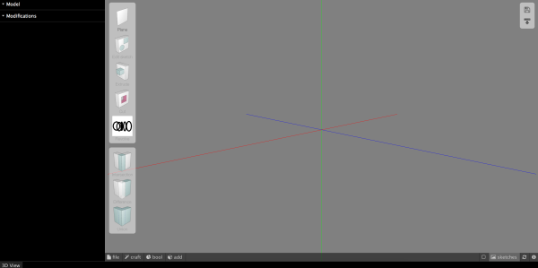
While still in its infancy, JS.Sketcher is seeking to fill that niche. It is 100% open-source, runs in your browser using only JavaScript, and is fully parametric (with both constraints and editable dimensions). At this time, available features are still pretty limited and simple. You can: extrude/cut, revolve, shell, and do boolean operations with solids. More advanced features aren’t available yet, but hopefully will be added in the future.

Continue reading “Open-Source Parametric CAD In Your Browser”

Laser-Cut ArcSin Dress Is Wearable Math

Using sewing simulation, 3D modeling and laser-cutting [Nancy Yi Liang] makes custom dresses that fit like a glove. Her project documentation walks us through all the steps from the first sketch to the final garment.

After sketching the design on paper, the design process moves into the digital domain, where an accurate 3D model of the wearer is required. [Nancy] created hers with Make Human, a free software that creates to-size avatars of humans from tape-measured parameters. Using the professional garment modeling software MarvelousDesigner (which offers a 30 day trial version), she then created the actual layout. The software allows her to design the cutting patterns, and then also drapes the fabric around the human model in a 3D garment simulation to check the fit. The result are the cutting patterns and a 3D model of the garment.

Continue reading “Laser-Cut ArcSin Dress Is Wearable Math”

Scratch Your Itch For 3D Modeling With BeetleBlocks

If you want to create a 3D model, you’ll probably either use a graphical CAD tool or a programming-based tool (like OpenSCAD). Although BeetleBlocks is graphical, it is more akin to OpenSCAD than a graphical CAD program. That’s because BeetleBlocks is–more or less–Scratch for 3D modeling.

Scratch is the graphical block-structured language developed by MIT for teaching kids to program. You may have seen Lego robots programmed with similar blocks as well as Android App Inventor. In this incarnation, the blocks control a virtual robot (the beetle) that can extrude a tube behind it as it moves. The beetle is reminiscent of the Logo turtle except the beetle moves in three dimensions. The system is actually closer to Snap, which is a reimplementation of Scratch that allows custom blocks.

Continue reading “Scratch Your Itch For 3D Modeling With BeetleBlocks”

BlocksCAD Is Browser-Based 3D Modeling That Teaches You CAD

Considering all of the projects the Raspberry Pi is used for now, the fact that it was originally envisioned to be an educational tool is sometimes forgotten. One of the tools commonly available with it is Scratch, a programming language that is easy to learn and can be seen as a gateway into other computer science realms. Building on this principle, MIT has come up with a new block-based educational tool called BlocksCAD.

BlocksCAD is essentially Scratch combined with OpenSCAD and allows the user to use blocks (similar to Scratch) to build a 3D model. The interface is fairly intuitive, and with some practice even complex shapes can be created using the tools available. Also, everything runs in a browser like the 3D modeling tool we featured a few days ago, so there isn’t anything to download or install.

The key to this project (like the key to Scratch) is that the user isn’t bogged down by syntax, which is often one of the largest hurdles for anyone who is just starting to learn to program. Since it’s possible to avoid syntax but still develop 3D models, this new tool should help anyone interested in the field of 3D modeling or CAD get a start without getting scared away too easily. Of course, if you do end up deep in the field of computer science and want to learn more about this project, the developers have opened up the source code as well.

Thanks for the tip, [Matt]!

3D Printing With 2D Inkscape Projections

If you had a formal drafting class, you probably learned about making orthographic projections–engineering drawings with multiple views (for example, top, front, and right). Even if you didn’t take the class, you’ve probably seen drawings like this where you view a 3D object as a series of 2D views from different angles.

These days, you are more likely to create a 3D model of an object, especially if you are going to 3D print it. After all, the 3D printer software is going to expect a model. When [Nightshade] wanted a laptop stand for his workbench, he started trying to do a 3D model. His final product though, was made by creating two views in Inkscape. They aren’t exactly orthographic projections of the final product, but the idea is similar.

Inkscape is a vector graphics program and generally creates SVG files, although it can also save EPS files. [Nightshade] used pstoedit to convert the EPS output to DXF format. DXF files are still two dimensional, but OpenSCAD can extrude DXF files into 3D shapes.

Just having a 3D shape of one view isn’t sufficient, though. The OpenSCAD script rotates the objects to the correct orientation and intersects them to form the final object. This is different from the usual cases of using Inkscape to trace a scan or generate simple text.

Continue reading “3D Printing With 2D Inkscape Projections”

3D Printing Helps Rekindle Old Love With An Uncommon Truck 

People may know many name and brands of cars and trucks, and there’s tons of scale models available for the average popular ones. What happens if your favorite truck is a 1960 Bucegi? You could do what [Arin] did and 3D print your own custom model.

[Arin] used to drive these machine back in his youth and it made an impression on him. In the few years of production, the 140HP V8 truck was adapted to all sorts of uses from farm trucks to military vehicles and even cranes.  The base truck and the desired configuration is modeled up in quite a bit of detail, then it’s 3D printed.

Once the printing is done the models are smoothed out using body filling primer paint, (and we imagine some fine sanding) , painted with acrylic paint, and assembled into an accurate model complete with working steering systems.

Below is a video showing assembly and painting and a second video showing off the steering system.

Continue reading “3D Printing Helps Rekindle Old Love With An Uncommon Truck “