The Stirling external combustion engine has fascinated gear heads since its inception, and while the technology has never enjoyed widespread commercialization, there’s a vibrant community of tinkerers who build and test their own takes on the idea. [Leo Fernekes] has been working on a small Stirling engine made from 3D printed parts and common hardware components, and in his latest video he walks viewers through the design and testing process.
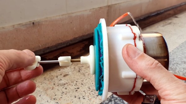
We’ve seen Stirling engines with 3D printed parts before, but in most cases, they are just structural components. This time, [Leo] really wanted to push what could be done with plastic parts, so everything from the water jacket for the cold side of the cylinder to the gears and connecting rods of the rhombic drive has been printed. Beyond the bearings and rods, the most notable non-printed component is the stainless steel spice shaker that’s being used as the cylinder.
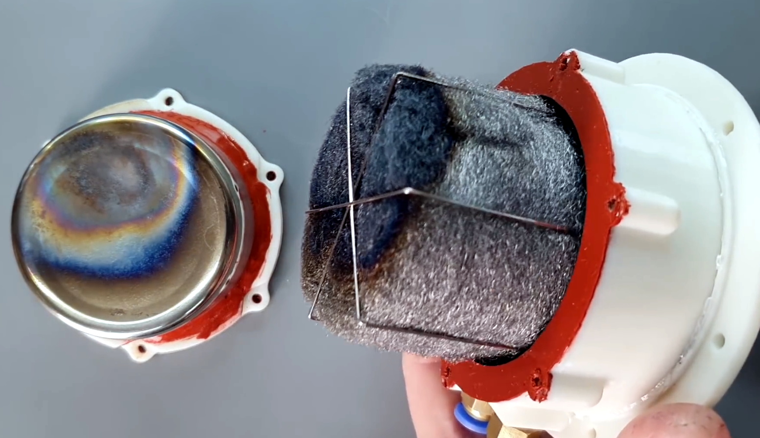
Mating the hot metal cylinder to the 3D printed parts naturally introduced some problems. The solution [Leo] came up with was to design a toothed collar to hold the cylinder, which reduces the surface area that’s in direct contact. He then used a piece of empty SMD component feed tape as a insulator between the two components, and covered the whole joint in high-temperature silicone.
Like many homebrew Stirling engines, this one isn’t perfect. It vibrates too much, some of the internal components have a tendency to melt during extended runs, and in general, it needs some fine tuning. But it runs, and in the end, that’s really the most important thing with a project like this. Improvements will come with time, especially once [Leo] finishes building the dynamometer he hopes will give him some solid data on how the engine’s overall performance is impacted as he makes changes.
If you’ve got a glass test tube laying around, putting together a basic Stirling engine demonstration is probably a lot easier than you might think. Commercial kits are also available if you’re looking for something more substantial, but even those can benefit from some aftermarket modifications. With a little effort, you’ll have a power plant ready for the surface of Mars in no time.
Continue reading “Spinning Up A Water Cooled 3D Printed Stirling Engine”