Hackaday Prize 2023: Bolt Bot Micro Servo Droids

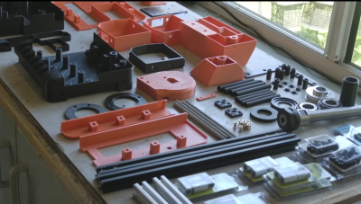
This Hackaday prize entry from [saul] is the beginning of a reconfigurable kit of 3D printed parts and servo motors for robotics learning. With just access to a printer, a few cheap-as-chips servo motors, an Arduino, and some nuts and bolts, you could be hacking together robot walkers within a few hours of starting!

Bolt Bots is very simple to understand, with all the mechanics and wiring out there in the breeze, but strictly for indoor use we reckon. If you want to add remote control to your application, then drop in one of the ubiquitous nRF24L01 boards and build yourself a copy of the remote control [saul] handily provides in this other project.

There really isn’t a great deal we can say about this, as it’s essentially a build kit with quite a few configuration options, and you just have to build with it and see what’s possible. We expect the number of parts to proliferate over time giving even more options. So far [saul] demonstrates a few flavors of ‘walkers’, a rudimentary ‘robot arm’, and even a hanging drawbot.

The bolt hardware can be found in this GitHub repo, and the remote control code in this second one.

Servo-based designs are sometimes sneered at due to their dubious accuracy and repeatability, but with a little of effort, this can be vastly improved upon. Also, multi-legged walkers need multiple servos and controllers to drive ’em. Or do they?

Continue reading “Hackaday Prize 2023: Bolt Bot Micro Servo Droids”

Arctos Robotics: Build A Robot Arm Out Of 3D Printer Spares?

ARCTOS is a 6-DOF robot arm based upon 3D printed mechanics running a modified version of GRBL firmware. Let’s get this straight now, the firmware is open source, but the hardware plans are a paid download, but for less than forty euros, we reckon the investment would be well worth it, judging from the quality of the build instructions and the software support already in place. Continue reading “Arctos Robotics: Build A Robot Arm Out Of 3D Printer Spares?”

Soldering Station Designed Around Batteries

Companies now are looking to secure revenue streams by sneakily locking customers into as many recurring services as possible. Subscription software, OS ecosystems, music streaming, and even food delivery companies all want to lock consumers in to these types of services. Battery-operated power tools are no different as there’s often a cycle of buying tools that fit one’s existing batteries, then buying replacement batteries, ad infinitum. As consumers we might prefer a more open standard but since this is not likely to happen any time soon, at least we can build our own tools that work with our power tool brand of choice like this battery-powered soldering station. Continue reading “Soldering Station Designed Around Batteries”

Testing Part Stiffness? No Need To Re-invent The Bending Rig

If one is serious about testing the stiffness of materials or parts, there’s nothing quite like doing your own tests. And thanks to [JanTec]’s 3-Point Bending Test rig, there’s no need to reinvent the wheel should one wish to do so.

The dial caliper can be mounted to a fixed height, thanks to a section of 3030 T-slot extrusion.

Some simple hardware, a couple spare pieces of 3030 T-slot extrusion, a few 3D-printed parts, and a dial indicator all come together to create a handy rig that will let one get straight to measuring.

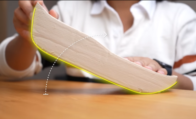
Here is how it works: stiffness of a material is measured by placing a sample between two points and applying a known force to the middle of the sample. This will cause the material to bend, and measuring how far a standardized sample deforms under a known amount of force (normally accomplished by a dial indicator) is how one can quantify a material’s stiffness.

When a material talks about its Young’s modulus (E) value, it’s talking about stiffness. A low Young’s modulus means a material is more elastic, a high value means the material is more stiff. (This shouldn’t be confused with strength or toughness, which are more about resistance to non-recoverable deformation, and resistance to fracture, respectively.)

Interested in results, but don’t want to get busy doing your own testing? Someone’s already been there and done that: here’s a great roundup of measurements of 3D-printed parts, using different filaments.

3D-Printable Foaming Nozzle Shows How They Work

[Jack]’s design for a 3D-printable foaming nozzle works by mixing air with a fluid like liquid soap or hand sanitizer. This mixture gets forced through what looks like layers of fine-mesh sieve and eventually out the end by squeezing the bottle. The nozzle has no moving parts but does have an interesting structure to make this possible.

The fine meshes are formed by multiple layers of bridged filament.

Creating a foam with liquid soap requires roughly one part soap to nine parts air. The idea is that the resulting foam makes more efficient use of the liquid soap compared to dispensing an un-lathered goop directly onto one’s hands.

The really neat part is that the fine mesh structure inside the nozzle is created by having the printer stretch multiple layers of filament across the open span on the inside of the model. This is a technique similar to that used for creating bristles on 3D-printed brushes.

While this sort of thing may require a bit of expert tweaking to get the best results, it really showcases the way the fundamentals of how filament printers work. Once one knows the process, it can be exploited to get results that would be impossible elsewhere. Here are a few more examples of that: printing only a wall’s infill to allow airflow, manipulating “vase mode” to create volumes with structural ribs, and embedding a fine fabric mesh (like tulle) as either a fan filter or wearable and flexible armor. Everything’s got edge cases, and clever people can do some pretty neat things with them (when access isn’t restricted, that is.)

Tree Supports Are Pretty, So Why Not Make Them Part Of The Print?

Here’s an idea that [Nephlonor] shared a couple years ago, but is worth keeping in mind because one never knows when it might come in handy. He 3D printed a marble run track and kept the generated tree supports. As you can see in the image above, the track resembles a roller-coaster and the tree supports function as an automatically-generated scaffolding for the whole thing. Clever!

As mentioned, these results are from a couple of years ago; so this idea should work even better nowadays. Tree supports have come a long way since then, and are available in more slicers than just Cura.

Tree supports without an interface layer is easy mode for “generate me some weird-looking scaffolding”

If you’re going to do this, we suggest reducing or eliminating the support interface and distance, which is the spacing between the supports and the rest of the model. The interface makes supports easier to remove, but if one is intending to leave it attached, it makes more sense to have a solid connection.

And while we’re on the topic of misusing supports, we’d like to leave you with one more trick to keep in mind. [Angus] of Maker’s Muse tucked a great idea into one of his videos: print just the support structure, and use it as a stand for oddly-shaped objects. Just set the object itself to zero walls and zero infill, and the printer will generate (and print) only the support structure. Choose an attractive angle, and presto! A display stand that fits the object like a glove.

You can watch a brief video of the marble run embedded below. Again, tree supports both look better and are available in more slicers nowadays. Have you tried this? If so we’d love to hear about it, so let us know in the comments!

Continue reading “Tree Supports Are Pretty, So Why Not Make Them Part Of The Print?”

A Soft Soldering Jig For Hard Projects

We’ve seen some absolutely gorgeous freeform circuit sculptures. There’s a mystic quality to taking what has normally been hidden away for safety and reliability reasons and putting it on display for everyone to see. Of course, creating these unique circuit sculptures takes considerable time and effort. [Inne] created several silicone soldering jigs to help with these tricky joints.

While a vice or helping hands is crucial for many joints, when dealing with tiny SMD components and exacting angles, you need something a little more specialized. Double-sided tape is often recommended, but heat ruins the adhesive and SMD components like to stick to soldering iron tips. Since silicone tends to be heat resistant, it makes a decent material for soldering on. [Inne] uses a city analogy with the cups for soldering called plazas, each with a hole (called a manhole) leading to a foot-switch vacuum pump to keep parts in place. The OpenSCAD code is available on GitHub under a GPLv3 license. It generates a two-part mold that you can cast in A-8/A-15 silicone.

It’s a clever project that makes it far easier to assemble gorgeous circuit sculptures. We love the design and thought that went into it, particularly the naming scheme as we often find appropriately naming variables in OpenSCAD quickly becomes difficult.