Just in time for the back to school and holiday season, Makerbot has released their latest line of printers. The latest additions to the lineup include the new Makerbot Replicator+ and the Makerbot Replicator Mini+.
The release of these new printers marks MakerBot’s first major product release since the disastrous introduction of the 5th generation of MakerBots in early 2014. The 5th generation of MakerBots included the Replicator Mini, priced at $1300, the Replicator, priced at $2500, and the Replicator Z18, priced at $6500. Comparing the build volume of these printers with the rest of the 3D printer market, these printers were overpriced. The capabilities of these printers didn’t move many units, either (for instance, the printers could only print in PLA). Makerbot was at least wise enough to continue building the 4th generation Replicator 2X, a printer that was capable of dual extrusion and printing more demanding filaments.
The release of the Makerbot Replicator+ and the Makerbot Replicator Mini+ is the sixth generation of MakerBot printers and the first generation of MakerBot’s manufactured overseas. This new generation is a hardware improvement on several fronts and included a complete redesign of the Makerbot Replicator and the Replicator Mini. The Replicator Mini+ features a 28% larger build volume than the original MakerBot Replicator Mini and an easily removable Grip Build Surface that can be flexed to remove a printed part. The Replicator+ features a 22% larger build volume than the MakerBot Replicator and a new Grip Build Surface. The Replicator Mini+ is $1000 ($300 cheaper than its predecessor), and the Replicator+ is $2000 ($500 less expensive). Both new printers, and the old Replicator Z18, now ship with the improved Smart Extruder+.
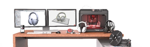
While the release of two new MakerBots does mean new hardware will make it into the wild, this is not the largest part of MakerBot’s latest press release. The big news is improved software. Makerbot Print is a slicer that allows Windows users to directly import 3D design files from SolidWorks, IGES, and STEP file formats. Only .STL files may be imported into the OS X version of the Makerbot Print software. MakerBot Mobile, an app available through the Apple Store and Google Play, allows users to monitor their printer from a smartphone.
Earlier this year, we wrote the Makerbot Obituary. From the heady days of The Colbert Report and an era where 3D printing would solve everything, MakerBot has fallen a long way. In the first four months of 2016, MakerBot only sold an average of about fifteen per day, well below the production estimated from the serial numbers of the first and second generation Makerbots, the Cupcake and Thing-O-Matic.
While this latest hardware release is improving the MakerBot brand by making the machines more affordable and giving the software some features which aren’t in the usual Open Source slicers, it remains to be seen if these efforts are enough. Time, or more specifically, the Stratasys financial reports, will tell.