The last year or two has seen relatively affordable multi-material printers hit the market, and the question that [Tom Nardi] and I were kicking around when he was writing up the 2025 year-in-review article was what it was going to mean for our folks. I don’t think he got it wrong per se, but his heading for that section “Grandma is 3D-Printing in Color” only tells half the story.
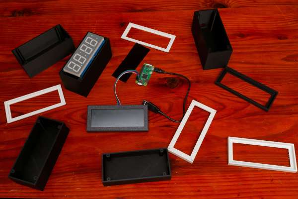
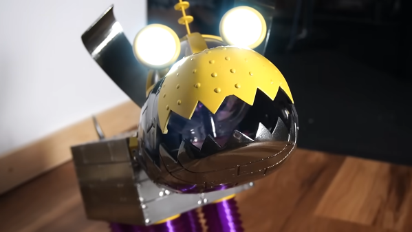
He did get that part right, though. We’ve certainly seen a flourishing of multi-material designs out there that take advantage of the availability of (usually) four colors. The ability to print in color has given life to the purely decorative models, of course. Think full-color Pokemon desktop toys, for instance. But even functional prints have benefited from contrasting color labels printed right into the box, not to even mention the multi-material supports that pull off easier and cleaner than ever before.
Since most of these multi-filament machines are pretty much locked down as far as hardware tinkering goes, our sights were firmly locked on what the end-user would do with the new capability. But we overlooked the third axis of 3D printering: the software hackers. And it’s precisely in this area of slicer and path-planning that we’ve seen some of the coolest developments this year. Why? Because people have the hardware in their hands that they need to test out the algorithms.
 FullSpectrum and the more recent ImageMap are two techniques to get the missing in-between colors out of a four-filament printer, and in particular ImageMap tries to get the job done faster, and with fewer purges. We are amazed to see two different approaches to color blending popping up in just a few months of each other, and we have no doubt that work on this is going to continue.
At the end of the day, this really is just “put new tools in the hands of creative hackers, and they’ll find new ways to use them”, so we shouldn’t have been surprised at all. But if this is what comes out of the commercialization of the multi-material printer, what’s going to come when some of the more esoteric machine designs go mainstream? We can’t wait to find out!