Xbee Controlled, Granite-wrapped Clock Travels Into Future

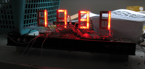
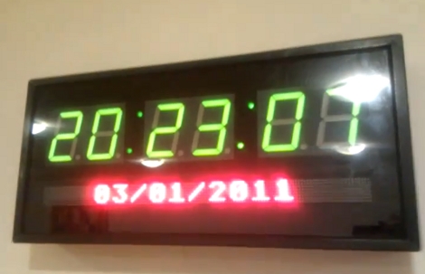
From the looks of it this clock is a couple of months ahead of its time. [Oscar] built the clock (translated) taking time to add a lot of goodies into the mix. First up, the parts you see include six large 7-segment displays for hours, minutes, and seconds as well as an LED marquee which can scroll messages. Inside there’s a temperature and humidity sensor for environmental feedback, and an Xbee module which allows for wireless computer control. Time is kept by a DS1307 real-time clock, which is read by an Arduino Uno, then pushed to the display by the pair of I2C addressable SAA1064 drivers. The whole thing was enclosed in four sheets of granite for the box, and a pane of glass for the front. We sure hope it’s well anchored to that wall. You can see it ticking away after the break.

Continue reading “Xbee Controlled, Granite-wrapped Clock Travels Into Future” →
Electronic Dice Has Option For 20 Or 100 Sides

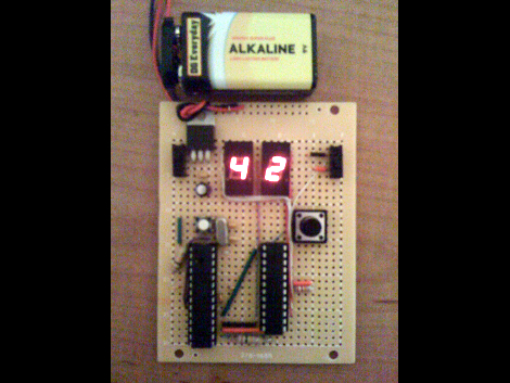
[Bluewraith] built himself an electronic dice using a 555 timer and 4017 counter. This is a classic project and he enjoyed doing it but wondered about making a 20-sided dice. So he grabbed his Arduino and got to work. A switch on the final project selects between 20 or 100 sides. He used a MAX7219 to control the 7-segment displays, and a standalone AVR chip for the rest of it.

If you missed it back in October you should also look in on this 6-sided dice. It also uses an AVR running the Arduino bootloader but a mercury switch allows the player to shake the box in order to start a roll.

One last note, we made a conscious decision to use the word ‘Dice’ instead of the grammatically correct ‘Die’ which is its singular version. We think ‘Die’ can be a bit too confusing and we’re not the only ones.

Wristwatch Board With Throwback Digits

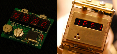
This wristwatch circuit board has some pretty interesting digits. They’re older components that give a classic look to your wristwatch display. On board you’ll find a PIC 16F628A running with an external clock crystal. The display isn’t always illuminated (kind of like Woz’s watch) in order to save the batteries, but can be woken up for a short time with the push of a button. The steam-punk-ish body seen to the left is the just first try. This guy has four more boards left so it should be fun to see what he comes up with.

[Via Hackaday Flickr Pool]

7-segment Sudoku

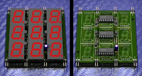
[John Sarik] keeps cranking out new ideas for his digital Sudoku project. This time he’s using 7-segment displays for each digit. The game play works the same as the Nixie Tube version, but this makes things quite a bit easier to build. The board above is one of the nine modules that make up the game. They each use three shift registers to drive the nine 7-segment displays. With the help of five resistors all of the multiplexing is addressed via the serial input on those chips.

Motorcycle Current Gear Indicator

[Vassilis Papanikolaou] just finished building a gear indicator for a motorcycle. This quite a simple implementation compared to some of the other vehicle information displays we’ve taken a look at. You should be able to build and install your own without breaking the bank. An ATtiny25 microcontroller reads data from a couple of hall effect sensors and the neutral switch, then displays the current gear on a 7-segment display.

There’s a magnet on the shifter and two hall effect sensors at the position for ‘gear up’ and ‘gear down’ shifting. The AVR chip keeps track of these and even stores the last position in EEPROM when you shut the bike off. If the device somehow gets off track, it will automatically recalibrate itself next time you shift into neutral, thanks to the bike’s neutral sensor switch.

Beginner Concepts: Binary-coded Decimal

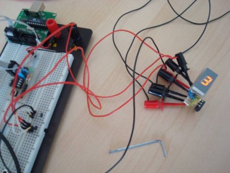
A rudimentary understanding of digital logic and simple integrated circuits is critical if you’re ever going to pull off some really gnarly hacks. [Daniel] put together an explanation about the use of 4511 BCD 7-segment drivers. These chips take binary data in and output decimal data to a 7-segment LED display. In short, they can read 0b1001 from input pins and light the numeral ‘9’ on the display. The best part is that you can build this example circuit in the Atanua logic simulator without ordering parts. We love zero-cost learning!