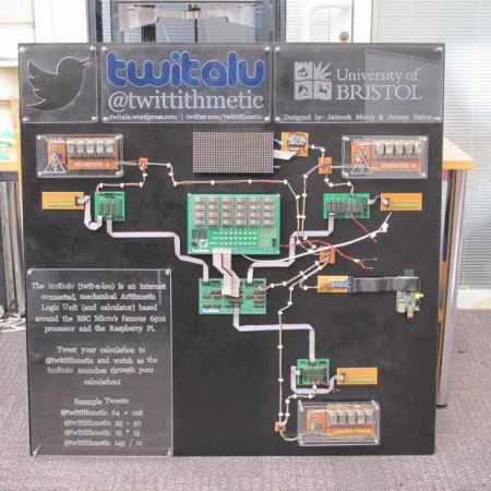
Two students at the University of Bristol wanted to create a computer to demonstrate how ALUs work. The result is the TwitALU, a Twitter connected mechanical calculator.
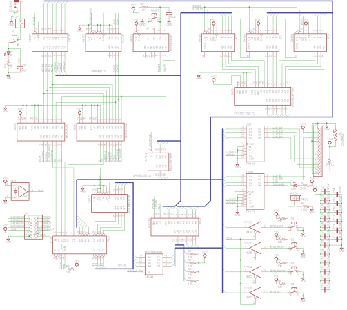
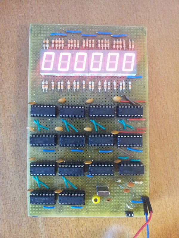
The device uses a custom 7400 series ALU based on the famous MOS 6502 processor. Instead of doing the calculations on a silicon die, the ALU drives mechanical relays. This produces a nice clicky-clacky sound as the calculation is computed.
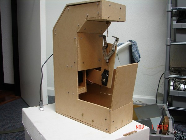
To start a calculation, you tweet @twittithmetic with your input. A Raspberry Pi is used to load the instructions into the ALU. Once the computation is done, it’s tweeted back to you and displayed on the Nixie tube display. It’s not efficient, or fast, but it does the job of demonstrating the inner workings of the device while doing simple math.
The device’s schematics are all available on the website, and are helpful for understanding how a simple ALU works. After the break, check out a quick clip of the TwitALU in action.
Continue reading “A Twitter Connected Mechanical Calculator”