Dead-Bug Logic Probe In A Magic Marker

Logic probes are simple but handy tools that can be had for a couple of bucks. They may not be the sexiest pieces of test gear, nor the most versatile, but they have their place, and building your own logic probe is a great way to understand the tool’s strength and weaknesses.

[Jxnblk]’s take on the logic probe is based on a circuit by [Tony van Roon]. The design hearkens back to a simpler time and is based on components that would have been easy to pick up at any Radio Shack once upon a time. The logic section is centered on the venerable 7400 quad 2-input NAND gate in the classic 14-pin DIP format. The gates light separate LEDs for high and low logic levels, and a 555 timer chip in a one-shot configuration acts as a pulse stretcher to catch transients. The DIP packages lend themselves to quick and dirty “dead bug” construction, and the whole thing fits nicely into a discarded marking pen.

dead-bug-logic-probe-in-marker-body

It’s a simple build and a nice form factor for a useful tool, but for an even slimmer package like an old syringe you’ll probably have to go with SMD components. And when you graduate from the simple logic probe, you might want to check out the capabilities of this smart probe.

8-bit Computer Made Solely From NAND Gates

As an electronics rookie, one of the first things they tell you when they teach you about logic gates is, “You can make everything from a combination of NAND gates”. There usually follows a demonstration of simple AND, OR, and XOR gates made from NAND gates, and maybe a flip-flop or two. Then you move on, when you want a logic function you use the relevant device that contains it, and the nugget of information about NAND gates recedes to become just another part of your electronics general knowledge.

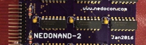
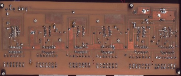
Not [Alexander Shabarshin] though. He’s set himself the task of creating an entire CPU solely from NAND gates, and he’s using 74F00 chips to give a hoped-for 1MIPS performance.  His design has an 8-bit data bus but a 4-bit ALU, and an impressive 2-stage pipeline and RISC instruction set which sets it apart from the computers most of us had when 74-series logic was a much more recent innovation. So far he has completed PCBs for a D-type flip-flop and a one-bit ALU, four of which will work in parallel in the final machine

Unsurprisingly, we have maintained a keen interest in TTL computers here at Hackaday for a very long time. You might say that we have featured so many for the subject to deserve a review article of its own. There is the ASAP-3, the Magic-1, the Duo Basic, the Apollo181, the unnamed CPU made by [Donn Stewart], the BMOW, and a clone of the Apollo Guidance Computer. But what sets [Alexander’s] project aside from all these fine machines is his bare-metal NAND-only design. The other 74-series CPU designers have had the full range of devices such as the 74181 ALU at their disposal. By studying the building blocks at this most fundamental level a deeper understanding can be gained of the inner workings of parts normally represented just as black boxes.

One of the briefs for writing a Hackaday article is that if the subject makes the writer stop and read rather than skim over it then it is likely to do so for the reader too. This project may not yet have delivered a working CPU, but its progress so far is interesting enough for an in-depth read. Definitely one to watch.

Spit Out VGA With Non-Programmable Logic Chips

It’s not uncommon to bitbang a protocol with a microcontroller in a pinch. I2C is frequently crunched from scratch, same with simple serial protocols, occasionally complex systems like Ethernet, and a whole host of other communication standards. But VGA gets pretty tricky because of the timing requirements, so it’s less common to bitbang. [Sven] completely threw caution to the wind. He didn’t just bitbang VGA on an Arduino, but he went one step further and configured an array of 7400 logic chips to output a VGA signal.

[Sven]’s project is in two parts. In part one, he discusses choosing a resolution and setting up the timing signal. He proceeds to output a simple(-ish) VGA signal that can be displayed on a monitor using a single gate. At that point only a red image was displayed, but getting signal lock from the monitor is a great proof of concept and [Sven] moved on to more intricate display tricks.

With the next iteration of the project [Sven] talks about adding in more circuitry to handle things like frame counting, geometry, and color. The graphics that are displayed were planned out in a simulator first, then used to design the 7400 chip configuration for that particular graphic display. It made us chuckle that [Sven] reports his monitor managed to survive this latest project!

We don’t remember seeing non-programmable integrated circuits used for VGA generation before. But bitbanging the signal on an Arduino or from an SD card slot is a great test of your ability to calculate and implement precise timings with an embedded system. Give it a try!

Continue reading “Spit Out VGA With Non-Programmable Logic Chips”

The Design And Fabrication Of A Digital Clock

boarddesign

This clock is the first thing that [Kevin] ever made, way back before the Arduinofication of making, and long before the open hardware community exploded, and before the advent of cheap, custom PCBs. It’s an elegant design, with six seven-segment displays, a time base derived from line frequency, controlled entirely by 74-series logic chips. There was only one problem with it: it kinda sucked. Every so often, noise would become a factor and the time would be displayed as 97:30. The project was thrown in the back of the closet, a few revisions were completed, and 13 years later, [Kevin] wanted to fix his first clock.

The redesign used the same 1Hz timebase to control the circuitry, but now the timebase is controlled by a DS3231 RTC with an ATtiny85. The bridge rectifier was thrown out in favor of a much simpler 7805 regulator, and a new board was designed and sent off to OSHPark. Oh, how times have changed.

With the new circuitry, [Kevin] decided to construct a new case. The beautiful Hammond-esque enclosure was replaced with the latest and greatest of DIY case material – laser cut acrylic. Before, [Kevin] would put a jumper on the 1Hz timebase derived from the line frequency to set the clock – a task that makes plugging a clock in exactly at midnight a much simpler solution. Now, the clock has buttons to set the hours and minutes. Much improved, but still an amazing look at how far DIY electronics have come in a little over a decade.


Duo Basic: An All-Logic Chip Educational Computer

DUO

Way back before the days of microcomputers, a few very lucky students first got their hands wet with microcomputer trainers. These simple devices used common logic chips, lights, and switches to perform calculations; basically, a very small and simple computer. [Jack] has just released his DUO Basic 8-bit educational computer, a computer designed entirely around logic chips just as was done in the olden days.

The entire computer except for a single EEPROM giving the computer 256 bytes of ROM, three registers, and two instructions (condition jmp and add). This allows for simple programs to be written just by flipping switches and hitting buttons – it doesn’t get much more ‘bare metal’ than that.

[Jack] has an online assembler and emulator for the DUO Basic along with a few example assembly programs. Of course, all the schematics and block diagrams are available on his site, along with a nice introductory video, shown below.

Continue reading “Duo Basic: An All-Logic Chip Educational Computer”

An Overly-Complicated Logic Chip Clock

Clock

When a normal alarm clock just won’t do, the only option is to build your own, entirely out of discrete logic chips. [jvok] built this alarm clock for last year’s 7400 Logic Competition. In a desire to go against the grain a little bit, [jvok] decided to use 4000-series logic chips. It was allowed under the rules, and the result is a wonderful example of what can be done without a microcontroller.

Most clock projects we’ve seen use a single button to increase each digit. [jvok] wanted to do something unique, so he is able to set his clock with a ‘mode’ button that allows him to independently set the hours, minutes, and seconds. He’s only ever seen this method of setting a clock’s time used with microcontroller-based projects, and translating even that simple code into pure circuitry is quite impressive.

This clock also includes an alarm function, set by a bunch of DIP switches in binary coded decimal. It’s a great piece of work, and deserving of much more attention than it received during the Open Logic Competition.

A Twitter Connected Mechanical Calculator

The TwitALU

Two students at the University of Bristol wanted to create a computer to demonstrate how ALUs work. The result is the TwitALU, a Twitter connected mechanical calculator.

The device uses a custom 7400 series ALU based on the famous MOS 6502 processor. Instead of doing the calculations on a silicon die, the ALU drives mechanical relays. This produces a nice clicky-clacky sound as the calculation is computed.

To start a calculation, you tweet @twittithmetic with your input. A Raspberry Pi is used to load the instructions into the ALU. Once the computation is done, it’s tweeted back to you and displayed on the Nixie tube display. It’s not efficient, or fast, but it does the job of demonstrating the inner workings of the device while doing simple math.

The device’s schematics are all available on the website, and are helpful for understanding how a simple ALU works. After the break, check out a quick clip of the TwitALU in action.

Continue reading “A Twitter Connected Mechanical Calculator”