[Czar] was working on a project with the Raspberry Pi using the MCP3008 analog to digital converter. The surface mount SOIC version of this chip was slightly cheaper, and there’s always a way to make that work (Portuguese, Google Translation). How [Czar] did it is fairly impressive, as it’s a bit more flexible for breadboard designs than a through-hole version, and done correctly, is an extremely sturdy hack.
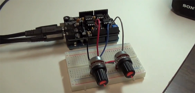
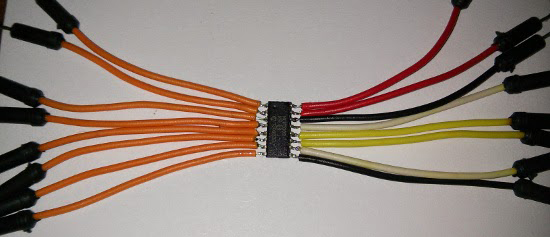
A few new leads needed to be soldered onto the SOIC package, and for this [Czar] chose jumper wires. This makes each pin easy to plug into a solderless breadboard, and since [Czar] was extremely clever, all the wires for power, ground, analog, and SPI are color coded.
Simply soldering a few jumper wires onto a chip won’t last for very long. To solve this problem, [Czar] potted the entire chip and its connections with hot glue. Probably not the best solution, and a heavy-duty epoxy would have been better, but the current build is more than enough to stand up to the relatively minor abuse it will receive on the workbench.