Hackaday Links Column Banner

Hackaday Links: June 13, 2021

When someone offers to write you a check for $5 billion for your company, it seems like a good idea to take it. But in the world of corporate acquisitions and mergers, that’s not always the case, as Altium proved this week when they rebuffed a A$38.50 per share offer from Autodesk. Altium Ltd., the Australian company whose flagship Altium Designer suite is used by PCB and electronic designers around the world, said that the Autodesk offer “significantly undervalues” Altium, despite the fact that it represents a 42% premium of the company’s share price at the end of last week. Altium’s rejection doesn’t close the door on ha deal with Autodesk, or any other comers who present a better offer, which means that whatever happens, changes are likely in the EDA world soon.

There were reports this week of a massive explosion and fire at a Chinese polysilicon plant — sort of. A number of cell phone videos have popped up on YouTube and elsewhere that purport to show the dramatic events unfolding at a plant in Xinjiang province, with one trade publication for the photovoltaic industry reporting that it happened at the Hoshine Silicon “997 siloxane” packing facility. They further reported that the fire was brought under control after about ten hours of effort by firefighters, and that the cause is under investigation. The odd thing is that we can’t find a single mention of the incident in any of the mainstream media outlets, even five full days after it purportedly happened. We’d have figured the media would have been all over this, and linking it to the ongoing semiconductor shortage, perhaps erroneously since the damage appears to be limited to organic silicone production as opposed to metallic silicon. But the company does supply something like 17% of the world’s supply of silicon metal, so anything that could potentially disrupt that should be pretty big news.

It’s always fun to see “one of our own” take a project from idea to product, and we like to celebrate such successes when they come along. And so it was great to see the battery-free bicycle tire pressure sensor that Hackaday.io user CaptMcAllister has been working on make it to the crowdfunding stage. The sensor is dubbed the PSIcle, and it attaches directly to the valve stem on a bike tire. The 5-gram sensor has an NFC chip, a MEMS pressure sensor, and a loop antenna. The neat thing about this is the injection molding process, which basically pots the electronics in EDPM while leaving a cavity for the air to reach the sensor. The whole thing is powered by the NFC radio in a smartphone, so you just hold your phone up to the sensor to get a reading. Check out the Kickstarter for more details, and congratulations to CaptMcAllister!

We’re saddened to learn of the passing of Dale Heatherington last week. While the name might not ring a bell, the name of his business partner Dennis Hayes probably does, as together they founded Hayes Microcomputer Products, makers of the world’s first modems specifically for the personal computer market. Dale was the technical guru of the partnership, and it’s said that he’s the one who came up with the famous “AT-command set”. Heatherington only stayed with Hayes for seven years or so before taking his a $20 million share of the company and retiring, which of course meant more time and resources to devote to tinkering with everything from ham radio to battle bots. ATH0, Dale.

Open-Source Thermostat Won’t Anger Your Landlord

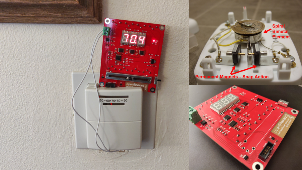
[Nathan Petersen] built a Hackable Open-Source Thermostat to smooth out temperature fluctuations caused by the large hysteresis of the bimetallic strip thermostat in his apartment. While it may be tempting to adjust the “anticipator” to take care of the problem or even replace the bimetallic thermostat with an electronic version, building your own thermostat from scratch is a good way to add to your project portfolio while making your way through college. Plus, he got to hone his hardware and software design chops.

The hardware is designed around the STM32, using a cheap, minimal variant since the device just needs to sense temperature and control the furnace in on-off mode. The TMP117 high-accuracy, low-power, temperature sensor was selected for temperature measurement since accuracy was an essential feature of the project. Dry-contact output for the furnace is via a normally-open solid state relay (opto-isolator). For the user interface, instead of going the easy-route and using an I2C/SPI OLED or LCD display, [Nathan] used three 7-segment LED displays, each driven by an 8-channel constant current driver. The advantage is that the display can be viewed from across the room, and it’s brightness adjusted via PWM. Temperature set-point adjustment is via a simple slide potentiometer, whose analog voltage is read by the micro-controller ADC. To remind about battery replacement, a second ADC channel on the micro-controller monitors the battery voltage via a voltage divider. The PCB components are mostly surface mount, but the packages selected are easy enough to hand solder.

[Nathan]’s Github repo provides the hardware and firmware source files. The board is designed in Altium, but folks using KiCad can use either the awesome Altium2KiCad converter or the online service for conversion. (The results, with some minor errors that can be easily fixed, are quite usable.) Serendipitously, his PCB layout worked like a charm the first time around, without requiring any rework or bodge wires.

The firmware is a few hundred lines of custom bare-metal C code, consisting of drivers to interface with the hardware peripherals, a UI section to handle the user interface, and the control section with the algorithm for running the furnace. [Nathan] walks us through his code, digging into some control theory and filtering basics. After making a few code tweaks and running the thermostat for some time, [Nathan] concludes that it is able to achieve +0.1°F / -0.5°F temperature regulation with furnace cycles lasting about 10-15 minutes (i.e. 4-6 cycles per hour). Obviously, his well insulated apartment and a decent furnace are also major contributing factors. Moving on, for the next version, [Nathan] wants to add data collection capabilities by adding some memory and SD card storage, and use an RTC to allow seasonal adjustments or time-based set-points.

This is his first attempt at a “functional’ useful project, but he does love to build the occasional toy, such as this POV Top.

Altium Has Its 2kicad Moment

Around these parts we tend to be exponents of the KiCad lifestyle; what better way to design a PCBA than with free and open source tools that run anywhere? But there are still capabilities in commercial EDA packages that haven’t found their way into KiCad yet, so it may not always be the best tool for the job. Altium Designer is a popular non-libre option, but at up to tens of thousands of USD per seat it’s not always a good fit for users and businesses without a serious need.

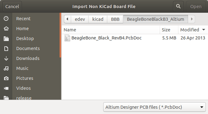
It’s hard to find an exciting photo of a dialog box

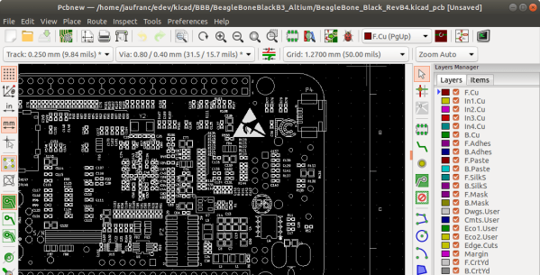
What do you do as a KiCad user who encounters a design in Altium you’d like to work with? Well as of April 3rd 2020, [Thomas Pointhuber] has merged the beginnings of a native Altium importer into KiCad which looks to be slated for the 6.0 release. As [Thomas] himself points out in the patch submission, this is hardly the first time a 3rd party Altium importer has been published. His new work is a translation of the Perl plugin altium2kicad by [thesourcerer8]. And back in January another user left a comment with links to four other (non-KiCad) tools to handle Altium files.

If you’d like to try out this nifty new feature for yourself, CNX has a great walkthrough starting at building KiCad from source. As for documents to test against the classic BeagleBone Black sources seen above can be found at on GitHub. Head past the break to check out the very boring, but very exciting video of the importer at work, courtesy of [Thomas] himself. We can’t wait to give this a shot!

Thanks for the tip [Chris Gammell]!

Continue reading “Altium Has Its 2kicad Moment”

Friday Hack Chat: Trusting The Autorouter

Ah, the autorouter. Inside every PCB design tool, there’s a function called the ‘autorouter’. This function, when used correctly, is able to automagically lay traces between pads, producing a perfect board in under a minute. The trouble is, no one uses it. We have been told not to trust the autorouters and we hear a lot of other dire warnings about it. The autorouter never works. The autorouter will put traces everywhere. The autorouter doesn’t consider floorplanning, and sometimes you’re going to get traces that go right through the edge of your board. Is avoiding the autorouter sound advice?

For this week’s Hack Chat, we’re talking about trusting the autorouter. The autorouter is just a tool, and like any tool, it will do exactly what you tell it. The problem, therefore, is being smart enough to use the autorouter.

Our guest for this week’s Hack Chat is Ben Jordan, Director of Community Tools and Content at Altium. Ben is a Computer Systems engineer, with 25 years experience in board-level hardware and embedded systems design. He picked up a soldering iron at 8, and wrote some assembly at 12. He’s also an expert at using an autorouter successfully.

In this Hack Chat, we’re going to talk to Ben about Altium, Circuit Maker, and how to get the best performance out of an autorouter. How do you set the autorouter up? How do you test your settings? What, actually, is the technology and math that goes into an autorouter? What is the best way to design a multilayer board? How do you do multiboard designs? And what’s the deal with mixed signals?

join-hack-chat

Our Hack Chats are live community events on the Hackaday.io Hack Chat group messaging. This Hack Chat is going down Friday, February 23rd at noon, Pacific time. Want to know what time this is happening in your neck of the woods? Here, look at the neat time zone converter thingy.

Click that speech bubble to the right, and you’ll be taken directly to the Hack Chat group on Hackaday.io.

You don’t have to wait until Friday; join whenever you want and you can see what the community is talking about.

MeatBagPnP Makes You The Automatic Pick And Place

It’s amazing how hackers are nowadays building increasingly complex hardware with SMD parts as small as grains of sand. Getting multilayer PCB’s and soldering stencils in small quantities for prototyping is easier than ever before. But Pick-and-Place — the process of taking parts and stuffing them on the PCB in preparation for soldering — is elusive, for several reasons. For one, it makes sense only if you plan to do volume production as the cost and time for just setting up the PnP machine for a small run is prohibitive. And a desktop PnP machine isn’t yet as ubiquitous as a 3D printer. Placing parts on the board is one process that still needs to be done manually. Just make sure you don’t sneeze when you’re doing it.

Of course the human is the slow part of this process. [Colin O’Flynn] wrote a python script that he calls MeatBagPnP to ease this bottleneck. It’s designed to look at a row in a parts position file generated from your EDA program and highlight on a render of the board where that part needs to be placed. The human then does what a robotic PnP would have done.

A bar code scanner is not necessary, but using one does make the process a bit quicker. When you scan a code on the part bag, the script highlights the row on the spreadsheet and puts a marker on the first instance of it on the board. After you’ve placed the part, pressing the space bar puts a marker on the next instance of the same value. The script shows it’s done after all parts of the same value are populated and you can then move on to the next part. If you don’t have a bar code scanner handy, you can highlight a row manually and it’ll tell you where to put that part. Check it out in the video below.

Of course, before you use this tool you need some prior preparation. You need a good PNG image of the board (both sides if it is double-sided) scaled so that it is the same dimensions as the target board. The parts position file generated from your EDA tool must use the lower left corner of the board as the origin. You then tell the tool the board dimensions and it scales up everything so that it can put the red markers at the designated XY positions. The script works for single and double-sided boards. For a board with just a few parts, it may not be worth the trouble of doing this, but if you are trying to manually populate a complex board with a lot of parts, using a script like this could make the process a lot less painful.

The project is still fresh and rough around the edges, so if you have comments or feedback to offer, [Colin] is listening.

[Colin]’s name ought to ring a bell — he’s the hacker who built ChipWhisperer which took 2nd Prize at The Hackaday Prize in 2014. The MeatBagPnP project is a result of having worked at building increasingly complex boards manually and trying to make the process easier. In addition to the walk-through of how the script works after the break we’ve embedded his other video from three years back when he was stuffing parts — including BGA’s — the hard way and then reflowing them in a Chinese oven with hacked firmware.

Continue reading “MeatBagPnP Makes You The Automatic Pick And Place”

Upverter Joins Altium

In a post on the Upverter blog today, [Zak Homuth], founder of the online EDA suite Upverter has announced they have been acquired by Altium.

The largest change in the announcement is the removal of Upverter’s paid professional tier of service. Now, the entirety of Upverter is free. Previously, this paid professional tier included CAM export, 3D preview, BOM management, and unlimited private projects for $1200 per seat per year.

Hackaday has taken a look at Upverter before in an book-length series of posts describing how to build a PCB in every software tool. While Upverter is a web-based PCB design tool that doesn’t respond to a right mouse click, the experience was pleasant overall. There are some interesting features in Upverter that make PCB design work fun — snap-to alignment of pads, a phenomenal number of ways to export your data — and it’s more than capable enough for the electronics hobbyist.

With the Altium announcement, [Zak] says Upverter will continue on its mission to create a system to design a complete product, from schematic to enclosure to firmware to BOM management.

Learn Advanced PCB Design For $200–Worth It?

[Helentronica] has been using Altium Designer to lay out PC boards since he was a student. Now as a freelancer, he felt like he didn’t quite know all that he wanted to know. Keep in mind he’d done multilayer boards with BGAs and LVDS routing, so he was no neophyte. He decided to spend about $200 on an advanced course from Fedevel Academy. In this day where everything is free on the Internet, is it worth paying $200 to watch some videos?

[Helentronica] probably weighed the same question. However, he was interested in the course project which is an open-source computer module with an i.MX6 processor, 1 GB of DDR3 SDRAM and lots of expansion options. In fact, the ad copy that sold him was:

You will be practicing on a real high-speed board with 1.2GHz CPU and DDR3, PCIE, SATA, HDMI, LVDS, 1Gb Ethernet and more

He completed the course. Was it worth it? We won’t spoil the story, but you should check out his post and find out. Even if you don’t want to drop $200 or you don’t use Altium, you will probably pick up some tips on PC board layout.

Continue reading “Learn Advanced PCB Design For $200–Worth It?”