Octopart And Altium Join Forces

Octopart, the search engine for electronic parts, is now a wholly owned subsidiary of Altium.

This acquisition is neither Altium’s first parts database purchase, nor is it Octopart’s first interaction with Altium. Ciiva, a parts and datasheet search engine was acquired by Altium a few years ago, and Altium Circuit Maker features an interface to the Octopart database.

Under the deal, Octopart will remain independent of Altium and operate out of their NYC office, and plans are for the part search engine to remain free and open.

Disclosure: Hackaday’s parent company, Supplyframe, also runs FindChips.com and Parts.io, component search tools.

Altium Gives Away The Farm With New Circuit Maker Software

Things are about to get interesting in the world of PCB design software for the open source hardware community. This week, Altium launched the open public beta for its new Circuit Maker software, and it’s a major change from what we looked at previously. Everything is free.

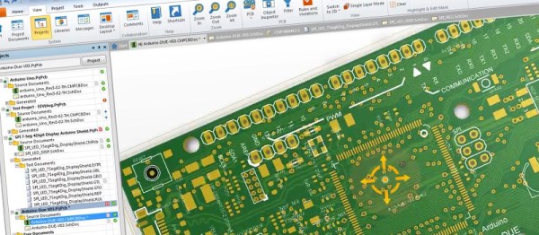
You heard that right, free. Unlimited board size, and unlimited layers – all free. And this isn’t some stripped-down, bare-bones software here. They’ve thrown in almost everything under the sun; a 3D viewer, team project collaboration, EagleCAD and DFX import, integrated Octopart supplier and pricing information, no commercial usage limits, and project sharing. And if that isn’t enough, the “engine” seems to be the exact same back-end that is used in the full $10,000 Altium Designer as well(with a bit easier to use user interface on top). This is a major departure from the pre-beta we covered back in September. Altium was going have board size and layer limits, with the ability to “upgrade” at a cost. So by now you’re thinking to yourself “OK, what’s the catch?” Well there are a few gotchas – but only a few.

The software uses cloud based storage for your project files, and is community based. It won’t work without an Internet connection, there is no local storage, and it forces you to share your projects with the world. You do get two “Sandbox” designs that you can hide from the world before you generate your gerber files, but after that, your project is online for the whole world to see. Will that be a deal killer for the OSHW community? We’ll find out soon enough.

One thing is for sure, anyone with a doggy Internet connection is not going to enjoy using Circuit Maker (we’re hoping they remove that limitation in the final product). And as with any cloud based service, we wonder how many people will be willing to trust their designs to a free service that could be turned off on a whim? Or will the unlimited board size and layers, combined with Altium’s name and robust software win people over in the end?

If you want to see in-depth review of Circuit Maker, we highly recommend you watch the video after the break.  [Dave Jones] of the eevblog, gives you a full rundown on the beta version. Dave’s in a unique place to review this software, not only has he been using Altium since the mid-80’s as a professional engineer, he’s also a former Altium employee.

Continue reading “Altium Gives Away The Farm With New Circuit Maker Software”

Valentine Heart

Animated LED Valentine Heart

With only a week left until Valentine’s day, [Henry] needed to think on his feet. He wanted to build something for his girlfriend but with limited time, he needed to work with what he had available. After scrounging up some parts and a bit of CAD work, he ended up with a nice animated LED Valentine heart.

[Henry] had a bunch of WS2812 LEDs left over from an older project. These surface mount LED’s are very cool. They come in a small form factor and include red, green, and blue LEDs all in a single package. On top of that, they have a built-in control circuit which makes each LED individually addressable. It’s similar to the LED strips we’ve seen in the past, only now the control circuit is built right into the LED.

Starting with the LEDs, [Henry] decided to build a large animated heart. Being a stickler for details, he worked out the perfect LED placement by beginning his design with three concentric heart shapes. The hearts were plotted in Excel and were then scaled until he ended up with something he liked. This final design showed where to place each LED.

The next step was to design the PCB in Altium Designer. [Henry’s] design is two-sided with large copper planes on either side. He opted to make good use of the extra copper surface by etching a custom design into the back with his girlfriend’s name. He included a space for the ATMega48 chip which would be running the animations. Finally, he sent the design off to a fab house and managed to get it back 48 hours later.

After soldering all of the components in place, [Henry] programmed up a few animations for the LEDs. He also built a custom frame to house the PCB. The frame includes a white screen that diffuses and softens the light from the LEDs. The final product looks great and is sure to win any geek’s heart. Continue reading “Animated LED Valentine Heart”

Reverse Engineering Altium Files

Several times in the last few weeks, I’ve heard people say, ‘this will be the last PCB I design in Eagle.’ That’s bad news for CadSoft, but if there’s one thing Eagle has done right, its their switch to an XML file format. Now anyone can write their own design tools for Eagle without mucking about with binary files.

Not all EDA softwares are created equally, and a lot of vendors use binary file formats as a way to keep their market share. Altium is one of the worst offenders, but by diving into the binary files it’s possible to reverse engineer these proprietary file formats into something nearly human-readable.

[dstanko.au]’s first step towards using an Altium file with his own tools was opening it up with a hex editor. Yeah, this is as raw as it can possibly get, but simply by scrolling through the file, he was able to find some interesting bits hanging around the file. It turns out, Altium uses something called a Compound Document File, similar to what Office uses for Word and PowerPoint files, to store all the information. Looking through the lens of this file format, [dstanko.au] found all the content was held in a stream called ‘FileHeader’, everything was an array of strings (yeah, everything is in text), and lines of text are separated by ‘|’ in name=value pairs.

With a little bit of code, [dstanko] managed to dump all these text records into a pseudo plain text format, then convert everything into JSON. You can check out all the code here.

CircuitMaker From Altium

Altium recently announced CircuitMaker, their entry into the free/low-cost PCB design tool market. They’re entering a big industry, with the likes of Eagle, KiCad, gEDA, and a host of other tool suites. We had a few minutes to talk with Max in the Altium booth at World Maker Faire, and even got a bit of time with the tool itself.

Hands on, it definitely has the look and feel of Altium Designer, right down to the familiar yellow and green boxes for schematic and sheet parts. Center stage was the 3D view, a feature which Altium has had in their software since the late 90’s.

CircuitMaker’s website is pushing the collaboration aspect of the software. Design choices can be reviewed and commented on in real-time. This also suggests that the data files will live in Altium’s own cloud storage system.

CircuitMaker is still in the pre-beta phase, but they’re looking for beta testers now, so head over to the site and sign up!

A Low Cost Arduino FPGA Shield

[technolomaniac] is kicking butt over at Hackaday Projects. He’s creating a low cost Arduino based FPGA shield. We’ve seen this pairing before, but never with a bill of materials in the $25 to $30 range. [technolomaniac’s] FPGA of choice is a Xilinx Spartan 6. He’s also including SDRAM, as well as an SPI Flash for configuration. Even though the Spartan 6 LX9 is a relatively small FPGA, it can pack enough punch that the Arduino almost becomes a peripheral. The main interconnect between the two will be the Arduino’s ability to program the Spartan via SPI. Thanks to the shared I/O pins though, the sky is the limit for parallel workflow.

[technolomaniac] spent quite a bit of time on his decoupling schematic. Even on a relatively small FPGA power decoupling is a big issue, especially when high speed signals come into play. Thankfully Xilinx provides guides for this task. We have to mention the two excellent videos [technolomaniac] created to explain his design. Documenting a project doesn’t have to be hours of endless writing. Sometimes it’s just easier to run a screen capture utility and click record. As of this writing, the schematic has just been overhauled, and [technolomaniac] is looking for feedback before he enters the all important layout stage. The design is up on his github repository in Altium format. Due to its high cost, Altium isn’t our first pick for Open Hardware designs. There are free viewers available, but [technolomaniac] makes it simple by putting up his schematic in PDF format (PDF link). Why not head over to projects and help him out?

Continue reading “A Low Cost Arduino FPGA Shield”

Update: Home Security Monitoring Prototype

home-security-monitoring-prototype-update-1

This project is about home security monitoring, but the update is crack for electronics designers. [Simon Ludborzs] continues to work on his prototype and he’s fantastic about sharing his success and failure in a conversational manner.

In April we saw his initial design which combined a SIM900 GSM modem with his own board to let him monitor his home security system without hiring a monthly service. Above you can see a snap of his latest prototype. It’s not fully populated as he’s testing the power supply… which in this state puts out 0V. Obviously that’s not up to his design specification so he started hunting around for the issue. He tells a tale of woe which is near to our hearts. He removed Q6, which is BC807 transistor, in order to test the FET used on the board. This brought it to life and had him looking into the datasheet of the part and its footprint in Altium. The footprint is right, the schematic symbol is wrong. There’s a lucky fix though. Above you can see the original design. The fix was just to rotate the part. This is illustrated as a change in the layout, but it worked with the original pad location. They’re not square to the transistor’s legs but they do still fit the outline.

He goes on to stress test the PSU output and then discuss whether it’s enough for the rest of the project. All in all a fascinating read!