Get To Know 3½ Digit ADCs With The ICL71xx

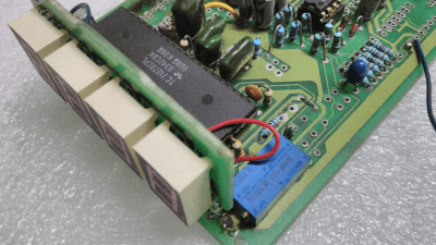
Riffling through my box of old projects, I came upon a project that I had built in the 80’s — an Automotive Multimeter which was published in the Dutch/British Elektor magazine. It could measure low voltage DC, high current DC, resistance, dwell angle, and engine RPM and ran off a single 9V battery. Besides a 555 IC for the dwell and RPM measurement and a couple of CMOS gate chips, the rest of the board is populated by a smattering of passives and a big, 40 pin DIP IC under the 3½ digit LCD display. I dug some more in my box, and came up with another Elektor project from back then — a True RMS digital Wattmeter with a 3½ digit LCD display that could measure up to 2kW. It had the same chip too. Some more digging, and I found a digital panel meter. This had a 7 segment LED display, but the chip was again from the same family.

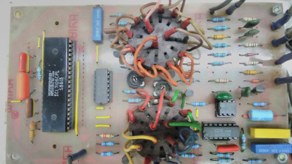
ICL7107 LED version
ICL7107 LED version

Look under the hood of any device with a 3½ or 4½ digit, 7 segment, LCD or LED from the ’80’s or ’90’s and you will likely spot this 40-pin DIP with the Intersil logo (although it was later also manufactured by many other fabs; Harris and Maxim among others). The chip doing all the heavy-lifting was likely to be the ICL7106 or ICL7107. These devices were described as high performance, low power, 3½ digit A/D converters containing seven segment decoders, display drivers, voltage reference and clock. In short, everything you needed to take a DC analog signal and display it. Over time, a whole series of devices were spawned:

  • 7106 – 3½ digit, 7 segment LCD
  • 7107 – 3½ digit, 7 segment LED
  • 7116 – 3½ digit, 7 segment LCD, with display HOLD (freeze)
  • 7117 – 3½ digit, 7 segment LED, with display HOLD (freeze)
  • 7126 – improved 7106
  • 7136 – improved 7126
  • 7135 – 4½ digit, 7 segment LCD

There were many similar devices available, but the ICL71xx series was by far one of the most popular, due to its easy of use, low parts count and single chip implementation. Here are several parts (linking to PDF datasheets) to illustrate my point: the TC14433/A needed several peripheral devices, ES5107 (a clone of a clone — read below), CA3162 (which has BCD output, and needs the CA3161 or similar to interface to a display), or the AD2020 (which too needed a lot of support circuitry).

The ICL71xx was the go-to device for a reason. Let’s take a look at the engineering and business behind this fascinating chip.

Continue reading “Get To Know 3½ Digit ADCs With The ICL71xx”

Analog To Digital Converter (ADC): A True Understanding

Back in the day where the microprocessor was our standard building block, we tended to concentrate on computation and processing of data and not so much on I/O. Simply put there were a lot of things we had to get working just so we could then read the state of an I/O port or a counter.

Nowadays the microcontroller has taken care of most of the system level needs with the luxury of built in RAM memory and the ability to upload our code. That leaves us able to concentrate on the major role of a microcontroller: to interpret something about the environment, make decisions, and often output the result to energize a motor, LED, or some other twiddly bits.

Often the usefulness of a small microcontroller project depends on being able to interpret external signals in the form of voltage or less often, current. For example the output of a photocell, or a temperature sensor may use an analog voltage to indicate brightness or the temperature. Enter the Analog to Digital Converter (ADC) with the ability to convert an external signal to a processor readable value.

Continue reading “Analog To Digital Converter (ADC): A True Understanding”

Beyond Measure: Instrumentation Amplifiers

In the first article about measurement systems we looked at sensors as a way to bring data into a measurement system. I explained that a sensor measures physical quantities which are turned into a voltage with a variable conversion element such as a resistor bridge. There will always be noise in any system, and an operational amplifier (op-amp) can be used to remove some of that noise. The example we considered used an op-amp in a differential configuration that removes any disturbance signal that is common to both inputs of the op-amp.

But that single application of an op-amp is just skimming the surface of the process of bringing a real-world measurement of a physical quantity into a digital system. Often, you’ll need to do more work on the signal before it’s ready for sampling with a digital-to-analog converter. Signal conditioning with amplifiers is a deep and rich topic, so let me make it clear that that this article will not cover every aspect of designing and implementing a measurement system. Instead, I’m aiming to get you started without getting too technical and math-y. Let’s just relax and ponder amplifiers without getting lost in detail. Doesn’t that sound nice?

Continue reading “Beyond Measure: Instrumentation Amplifiers”

Rasberry Pi Analog Input Using Only Passive Components

The Raspberry Pi is a very capable device whose hardware has been pushed to the limit in all sorts of interesting ways. But even the most ingenious of experimenters have to agree on one point; it doesn’t possess an analog-to-digital converter. If you want analog inputs you will have to buy or build them.

[Mincepi] has done just that, but not as you might expect by adding an integrated circuit on one of the Pi’s interfaces. Instead the circuit [Mincepi] is using consists only of passive components, measuring the time taken to discharge the parasitic capacitance of one of the Pi’s inputs from logic 1 voltage to logic 0 voltage through a resistor into the voltage to be measured. This is a long-established approach to A to D conversion, one that was achieved back in the day with purpose-designed timers as microprocessor ancillaries.

The problem is that the Pi does not have a timer peripheral, so [Mincepi] has used the shift registers that form part of the Pi’s SPI and PCM inputs to perform this task on two channels. A sample rate of 100kHz and 6-bit resolution is claimed, with enough voltage range for a 1V peak-to-peak audio signal to be sampled.

Of course, simplicity does not guarantee a good ADC, and this circuit does not perform very well. It is noisy, non-linear, and as [Mincepi] puts it, probably sensitive to temperature. And though [Mincepi] talks in detail about the software to drive it, none is forthcoming. To quote: “It doesn’t include code since I’m in the process of writing a proper sound device module. My previous code was a simple character device, but it worked just fine, and served to prove the concept.

We really want this to work, even if it’s not the best ADC ever. So we eagerly await the sound device module, and look forward to more news from the project.

This may be the simplest of simple ADCs we’ve yet featured here on Hackaday, but it’s not the first we’ve seen. There is this one using a comparator for example, or this one using a flip-flop. It is the essence of creative electronics to eke a function from a component that was never meant to be, please keep them coming!

Digital To Analog To Digital To Analog To Digital Conversion

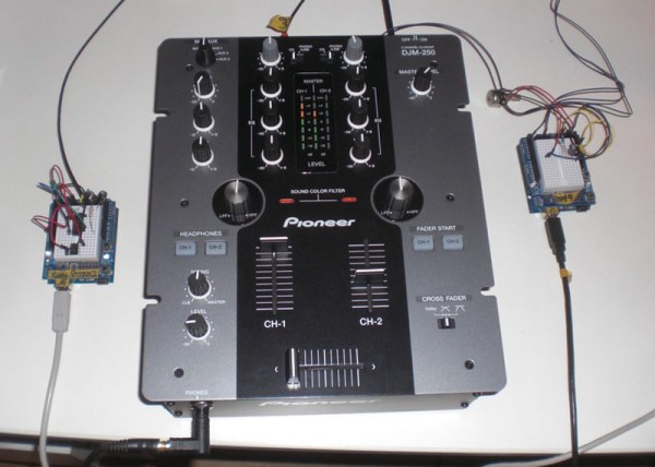
[Andy] had the idea of turning a mixing desk into a MIDI controller. At first glance, this idea seems extremely practical – mixers are a great way to get a lot of dials and faders in a cheap, compact, and robust enclosure. Exactly how you turn a mixer into a MIDI device is what’s important. This build might not be the most efficient, but it does have the best name ever: digital to analog to digital to analog to digital conversion.

The process starts by generating a sine wave on an Arduino with some direct digital synthesis. A 480 Hz square wave is generated on an ATTiny85. Both of these signals are then fed into a 74LS08 AND gate. According to the schematic [Andy] posted, these signals are going into two different gates, with the other input of the gate pulled high. The output of the gate is then sent through a pair of resistors and combined to the ‘audio out’ signal. [Andy] says this is ‘spine-crawling’ for people who do this professionally. If anyone knows what this part of the circuit actually does, please leave a note in the comments.

The signal from the AND gates is then fed into the mixer and sent out to the analog input of another Arduino. This Arduino converts the audio coming out of the mixer to frequencies using a Fast Hartley Transform. With a binary representation of what’s happening inside the mixer, [Andy] has something that can be converted into MIDI.

[Andy] put up a demo of this circuit working. He’s connected the MIDI out to Abelton and can modify MIDI parameters using an audio mixer. Video of that below if you’re still trying to wrap your head around this one.

Continue reading “Digital To Analog To Digital To Analog To Digital Conversion”